|
DG Systems
Bytemaster
System Cards
Keyboard
Printer A & B
Phideck
Disk Drives
Documentation
Software
Flyers
Magazine Ads
Mark-8 Minicomputer
Apple-1
MOS Kim-1
V C F
Imsai 8080
Kenbak-1
TV Typewriter
LSI ADM-3A
ASR-33
The Digital Group
| |

|
|
|
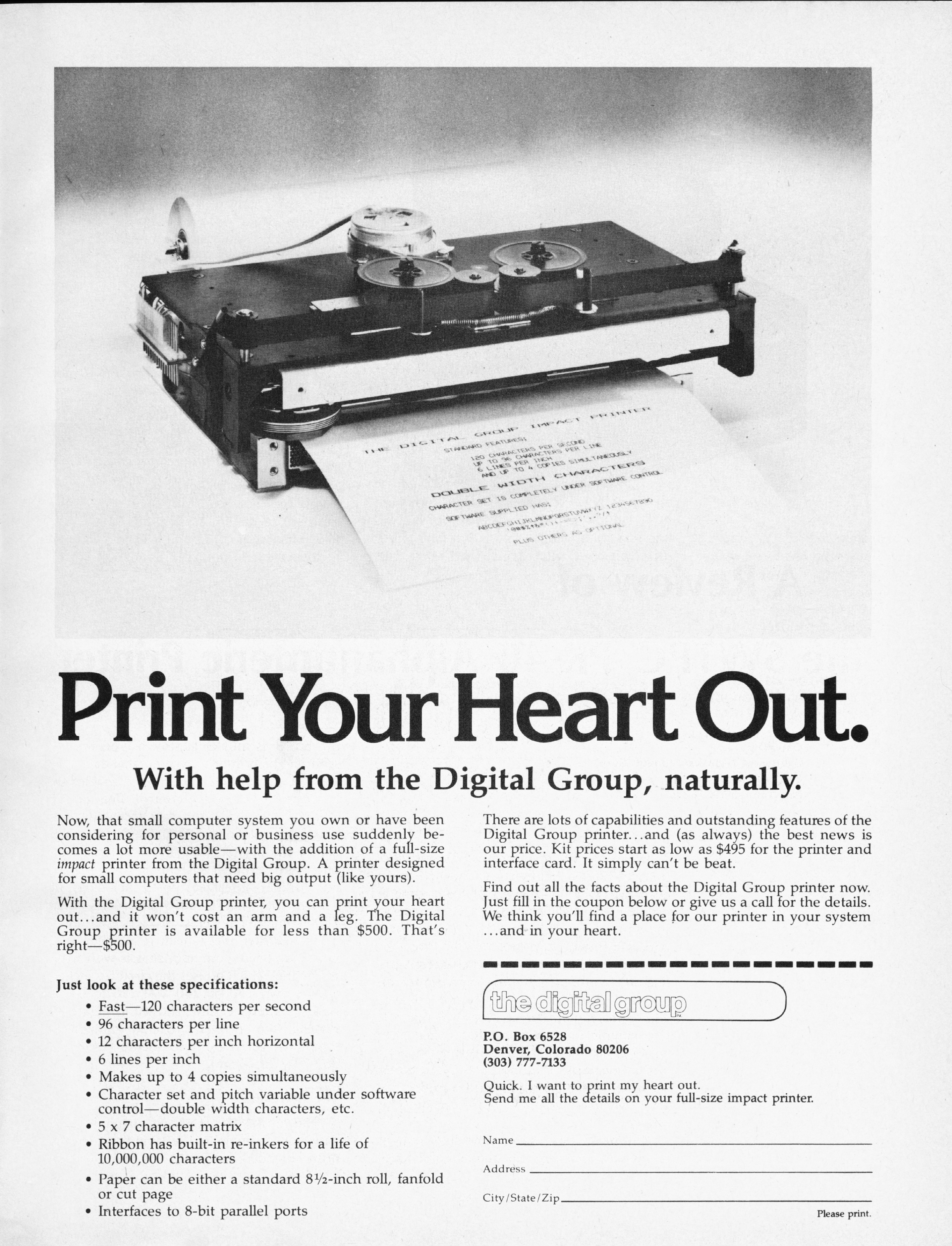
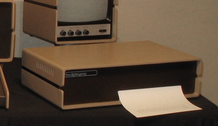
| The Digital Group Printer
Two versions of this printer were sold by Digital Group in the early
years, known only as the 'A' or the 'B' printers, they represent the bulk
of all printers sold by the company. In later years, a Centronics 779-1 was
introduced, but by this time the company was in trouble and it is unknown how
many were ever delivered.
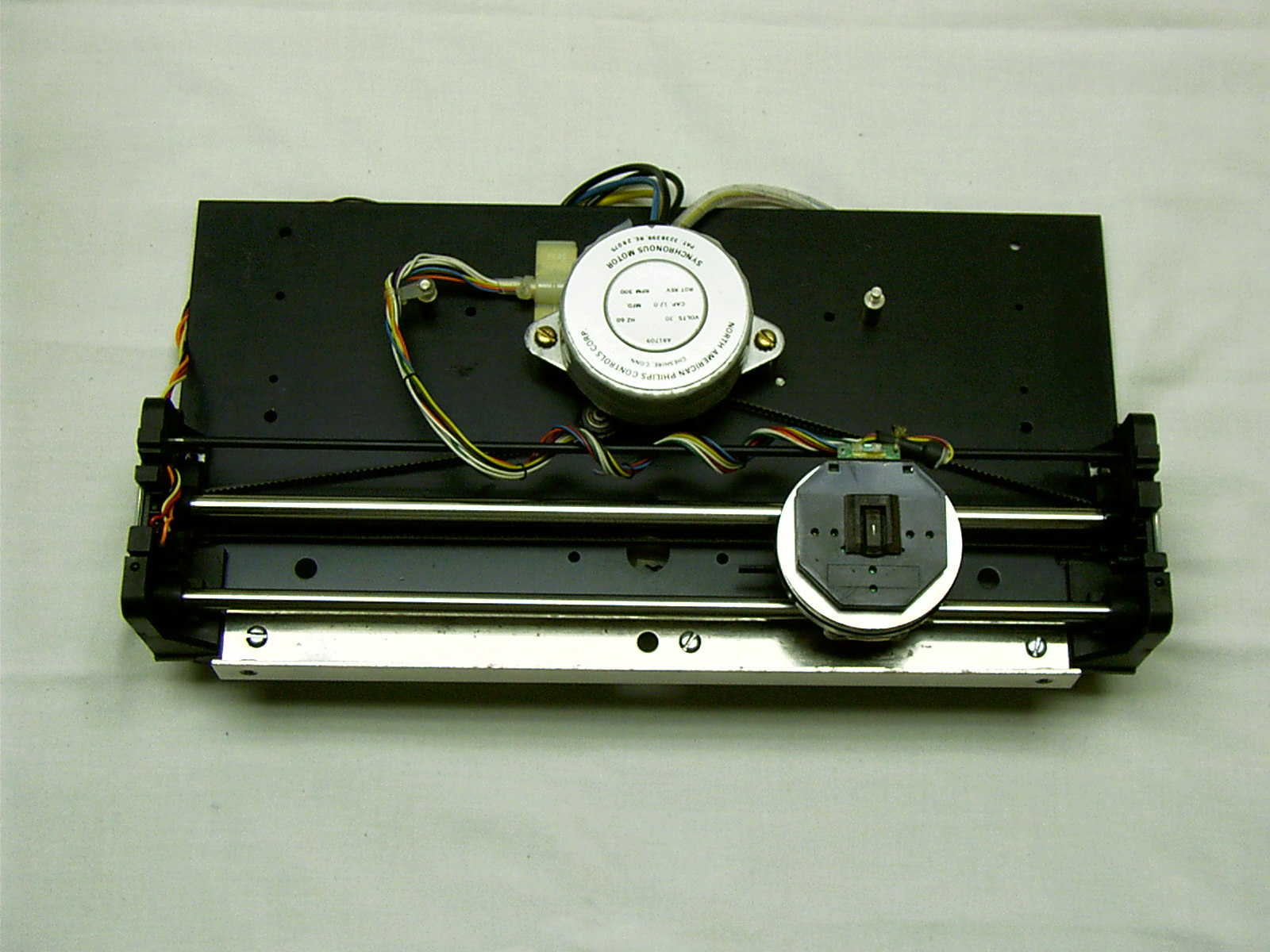
The printer is a 7-pin dot matrix printer that was manufactured by Practical
Automation of Shelton Connecticut for the Digital Group. This 96
column printer advertised a speed of 120 cps, and a software based
character set. Which meant that you could define your own characters:
double wide, bold, etc. Although this was billed as a plus, it basically
meant that the printer was "dumb"; it had no built in data
processing ability. Your main processor did all the dirty work: timing,
paper advance, printhead operations, etc.
One problem with this approach is the possibility
of a software bug instructing the paper advance solenoid to engage while
the printhead pins are extended... ouch. Hence the introduction of the
"B" controller. :)
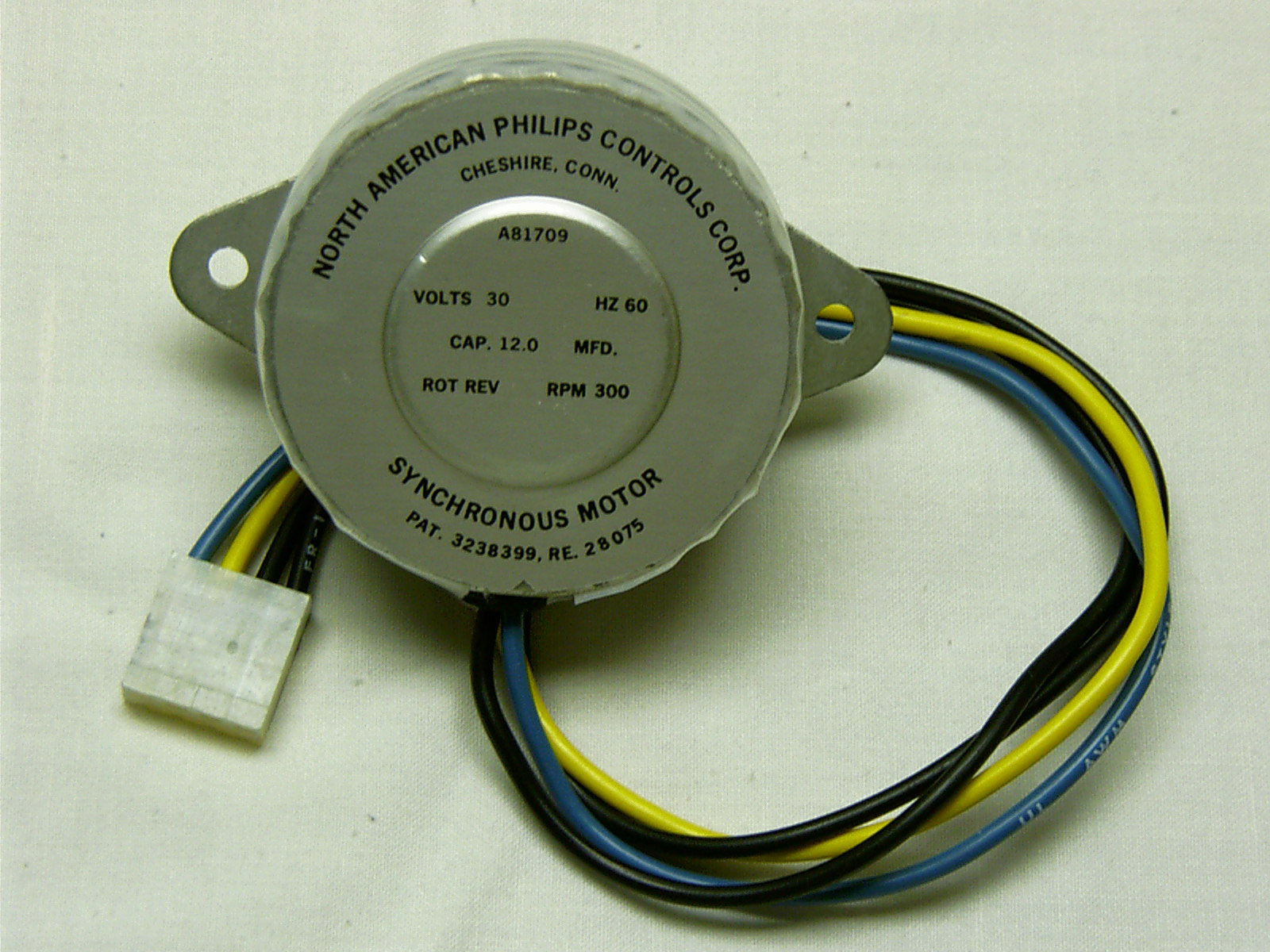
Since Dr. Suding, the designer of all things
Digital Group, was not a big fan of interrupt programming, background
printing was clumsy at best, but it worked well enough, bugs aside, and it
was great quality printing for the day at a reasonable price. The printer
sold complete for $495 in kit form, and $675 fully assembled. In today's
dollars (2008), that is $1760 and $2400 respectively--Can you imagine?
Competing
printers of this era sold for as much as $2700. At the time, there were new cars
selling for less.
|
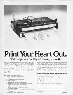
The first printer advertisement, Byte 3/77
|
|
|
This printer could also print up to four copies simultaneously, on
standard size letter or form feed paper, making it immediately useful for
business applications. Along with software available from the Digital
Group, this became one of the first hobbyist computers to make the
transition to business computing, where the big money was thought to be. One
other failing of this printer if used with the factory cabinet, was the
wholly impractical requirement to remove the cover in order to add paper--and
only half a roll would fit!
Almost immediately, after-market kits were available to place the paper
roll external to the printer.
I searched for one of these for a very long time before Bruce Damer of The
Digibarn offered me his--knowing it would be carefully restored.
Just as I was completing restoration of the mechanism, I was able to find
TWO more of them! When it rains... Anyway, the other two I picked up were
in just awful condition. I cannibalized a few parts from them to make the
Digibarn printer complete. The comments and photos on this page
detail the restoration of the Digibarn printer.
|
| The Restoration
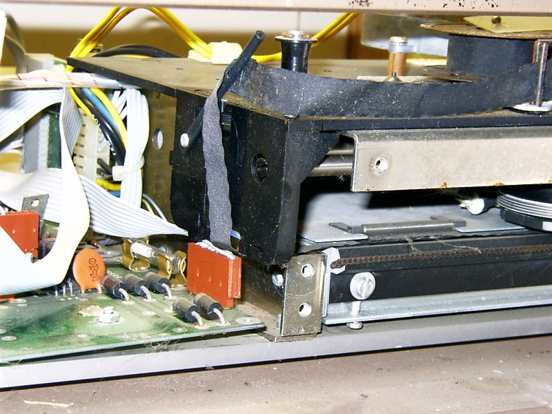
When I received the printer, the first thing I noticed was that the
California humidity had done it no favors. Rust and corrosion were
everywhere. Obviously, it was not operational. Fortunately, although the
rust was pervasive, it had not rendered anything
beyond salvation though some of the parts were in very rough shape and
required some real creativity to deal with--read on!
|
|
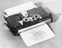
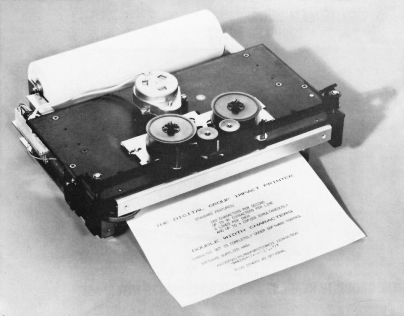
The Goal--from flyer 9
|
|
|
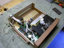
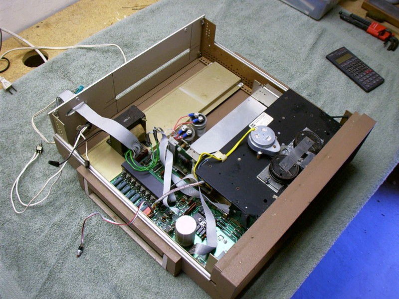
Non-DG cabinet in this photo
|
|
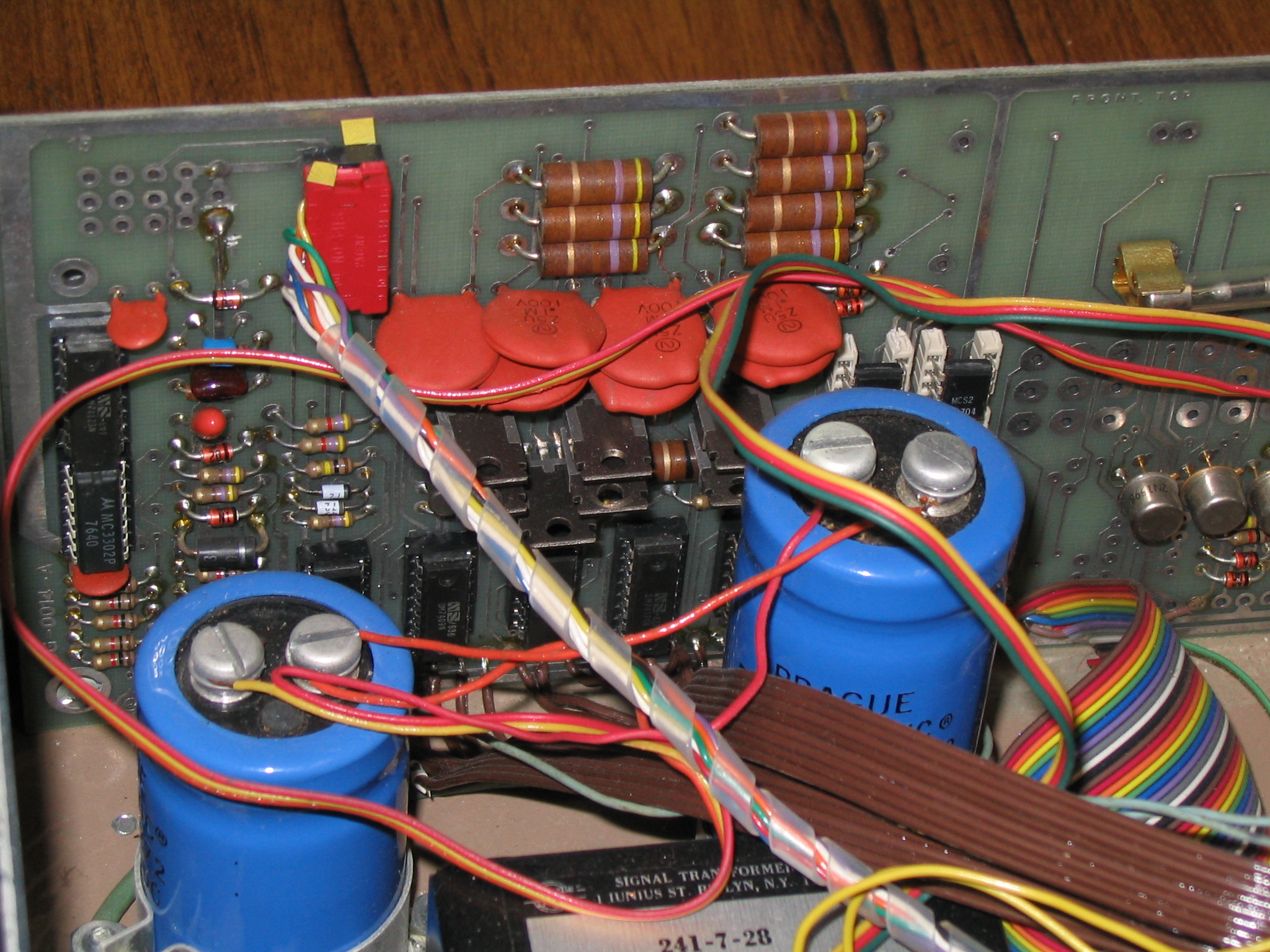
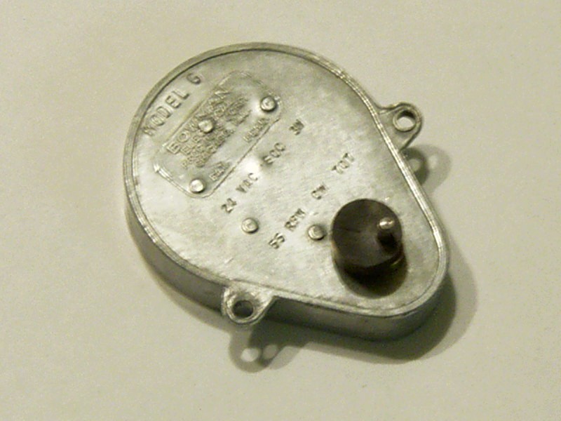
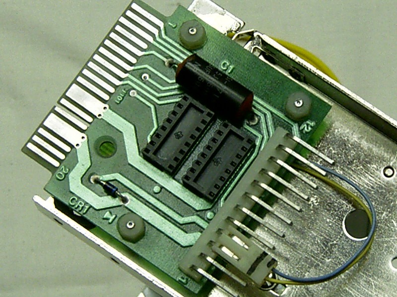
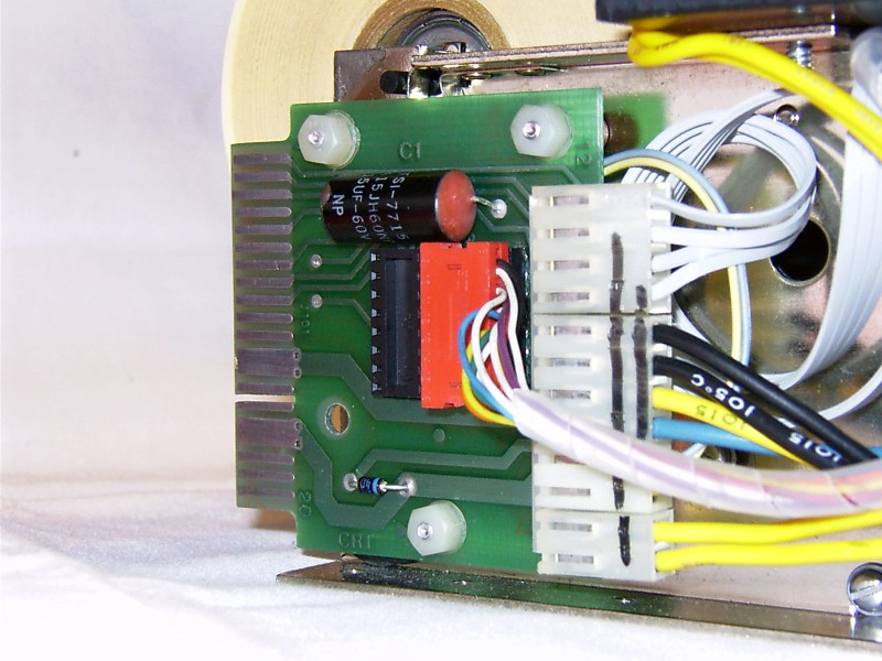
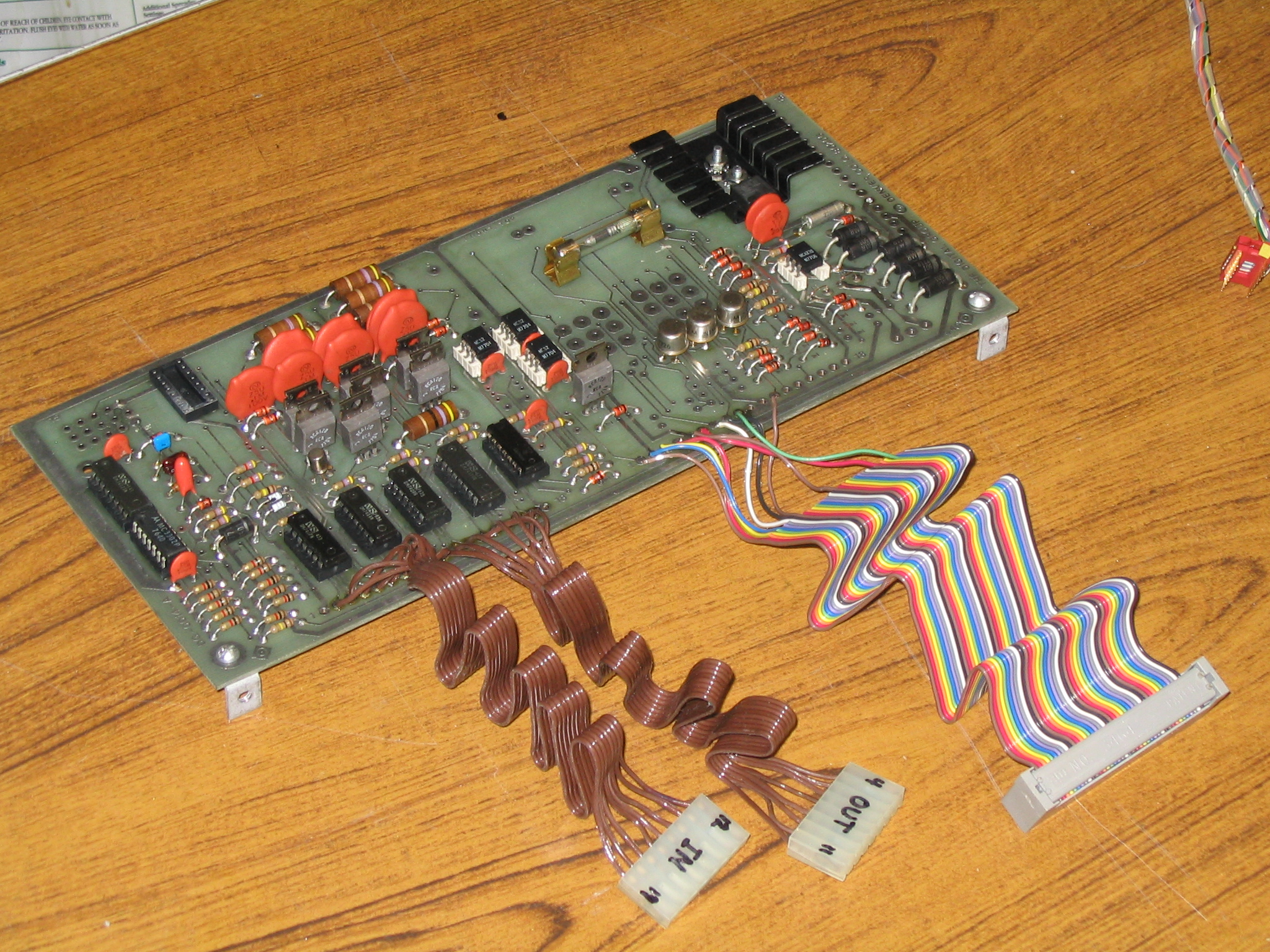
| The
control electronics in the Digibarn printer was a version B. The other two printers I
received later included an A electronics package in one of them, and I
chose to use that one in this printer--preferring the earlier versions of
stuff as I do. Eventually, I'll restore another with the B electronics. :)
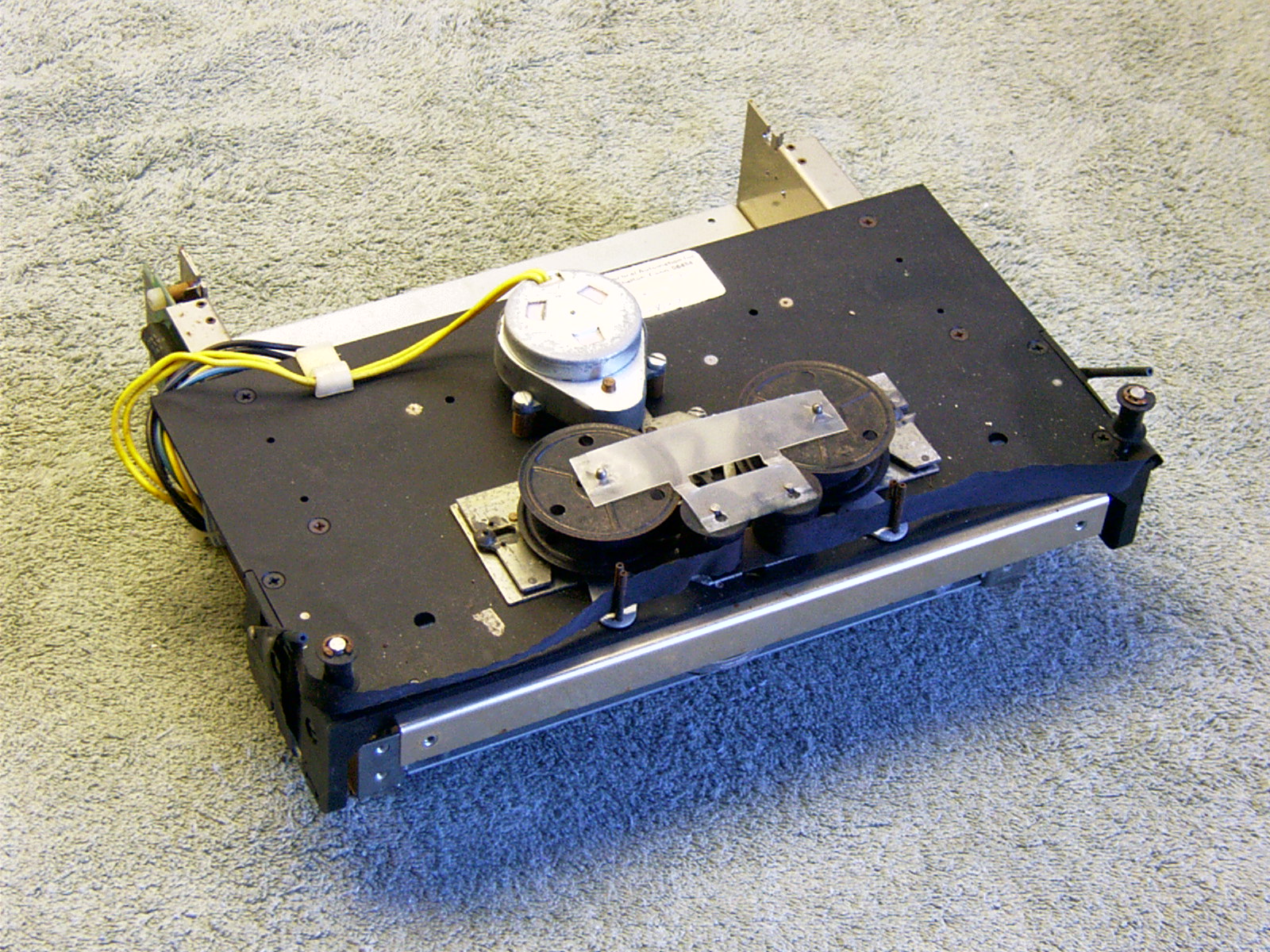
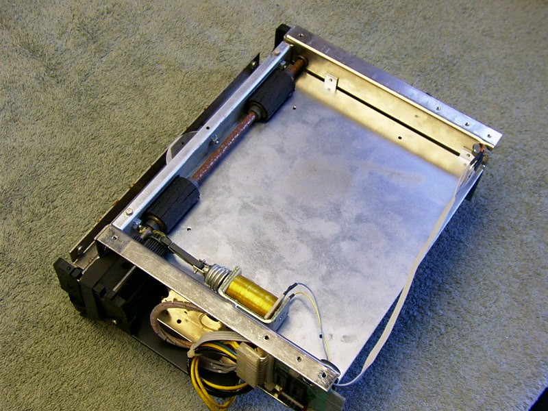
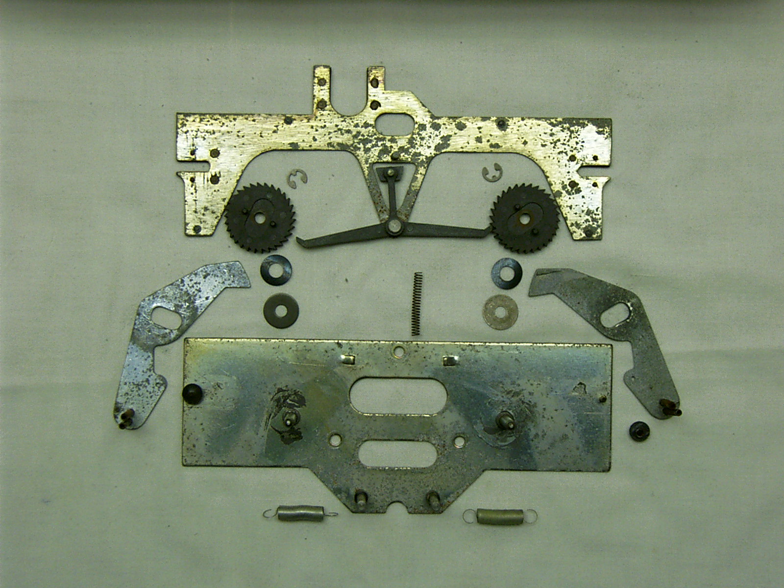
I
removed the printer from the non-original cabinet and began the
disassembly process, photographing it each step of the way, as at the time
I had no documentation to refer back to for reassembly. I also decided to
log my time in the project carefully, just because I wanted to know how
long a DG printer restoration would really take! Results? The progress on
printer mechanism alone, shown here in these pictures took just over 95
hours--I did not time the interface board or cabinet restoration. It was a
real pain keeping track of the time, and I gave up after the mechanism was
complete. You get the idea though--my kids miss me.
The print head was in pretty bad shape. The pins had all rusted in place,
and required great effort to remove, breaking a pin on one hammer in the
process. The repair was difficult. Finding practical repair materials, settling on a technique, and
doing the repair successfully on the first try, actually required a couple
dozen hours of planning and setup. This was the most challenging part of the repair.
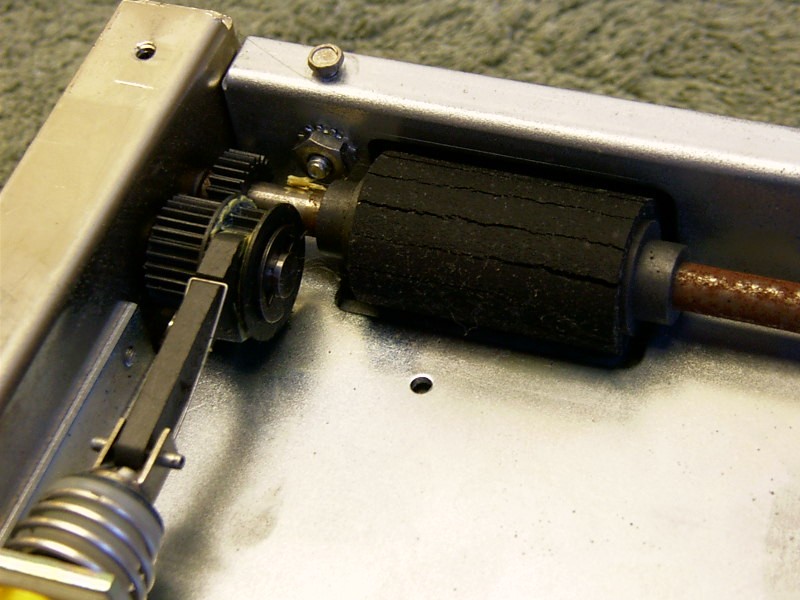
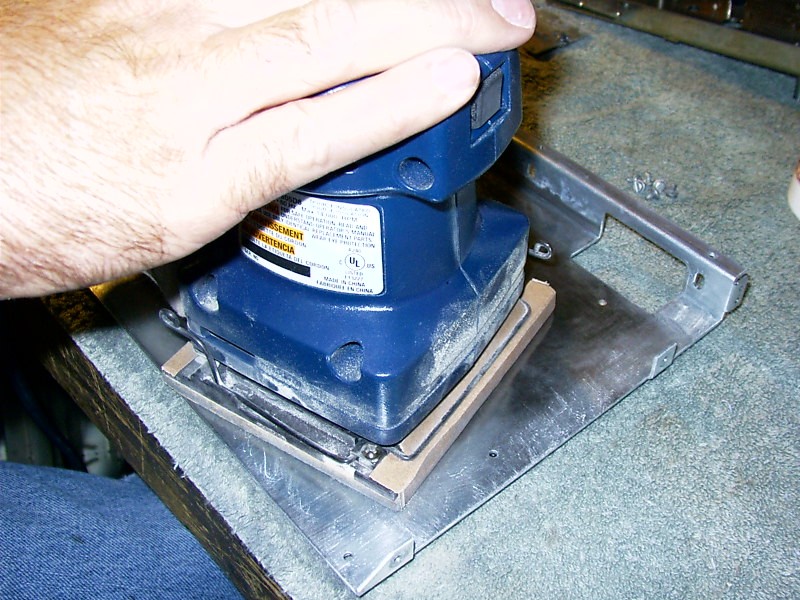
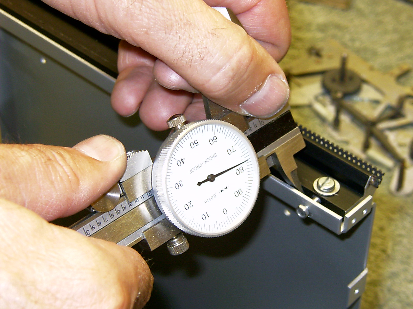
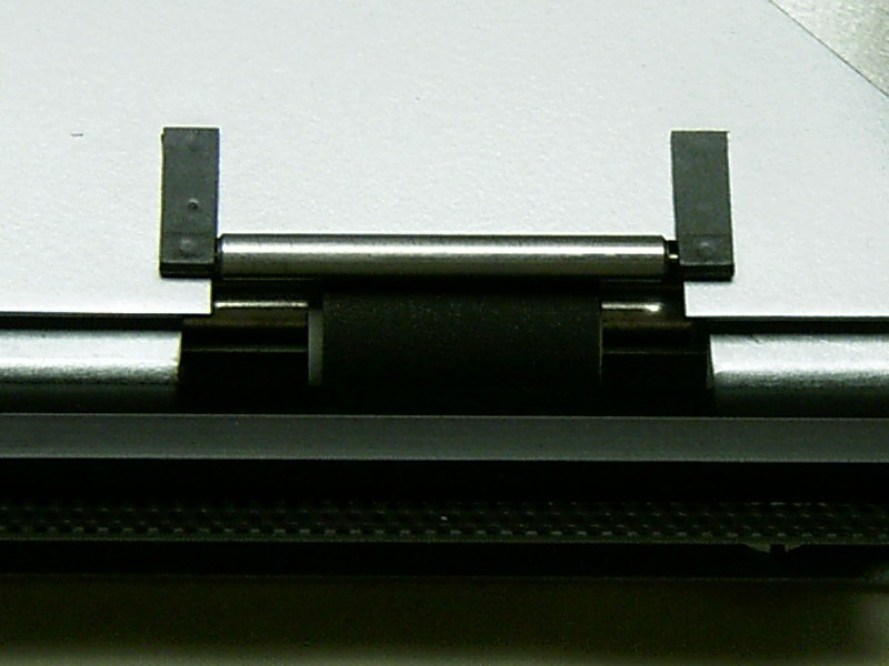
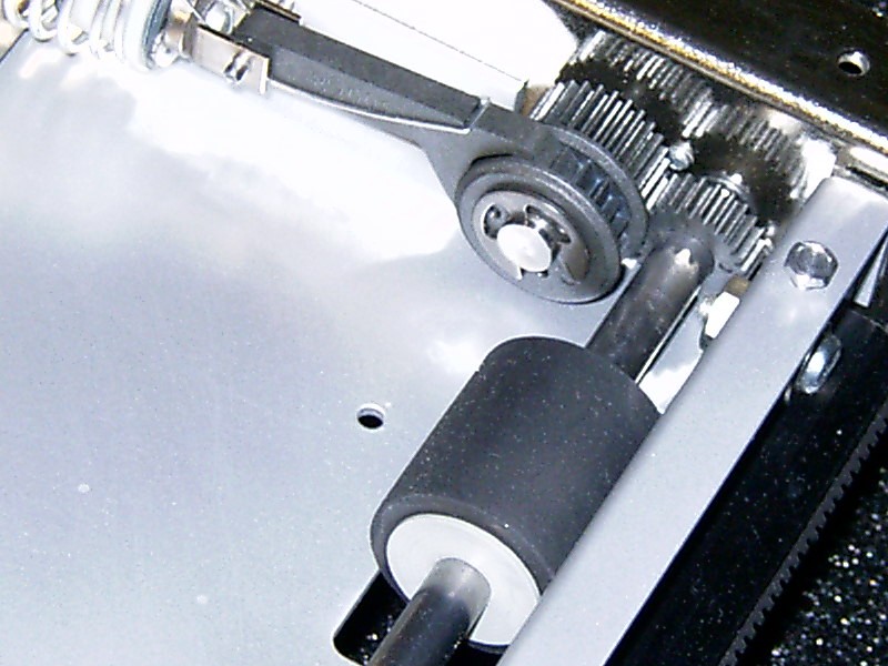
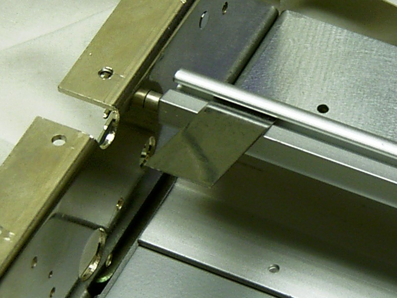
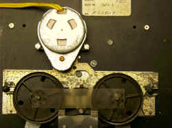
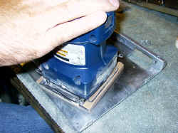
The next most difficult part was the
rubber rollers. I picked up a half-dozen junk printers from a second-hand
shop and reduced them to a pile of parts. Fishing through the pile, I
pulled a set of rollers that had the same shaft size, but were too large
otherwise. The oversized replacement rollers were re-sized by putting the
roller shaft in a drill, and then running the drill in a jig over a belt
sander. It took longer to set up the jig than to do the work, but the
result were better than I had hoped--I'd call it a perfect repair! (I now
have a lathe for such things--should I ever need to repeat this in the
future. :)
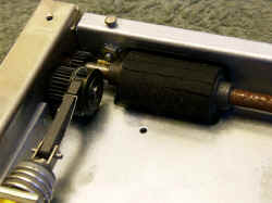
The
re-inker pads in the photos were an experiment. The original pads fell
apart during restoration--as I suspected they might from my initial
inspection. What I have in place
now is made from (get this!!) Mr. Clean's "Magic Sponge". What
can I say? Years later and it still works!
After all of the repairs and rebuilds, I tested all of the printer
mechanical actions, and everything worked fine. I then
began work on the cabinet and electronics. The cabinet was in great condition and needed
only minor paint work. The restore was pretty standard fare, taking a
couple dozen hours to break down, clean, rebrush all the aluminum and
airbrush the painted and anodized surfaces where needed to pretty them up
a bit. Ahhh!
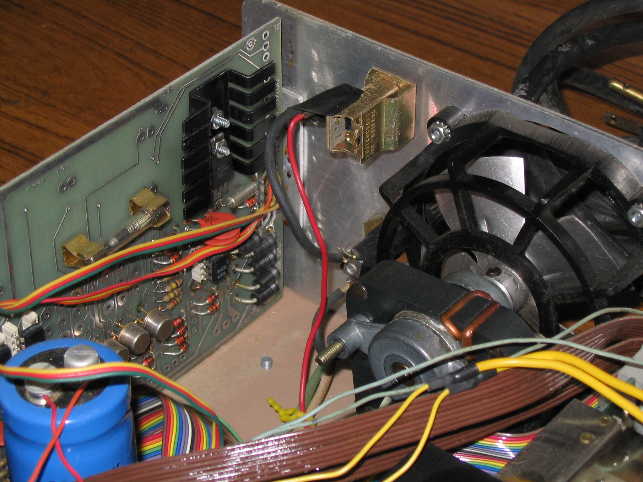
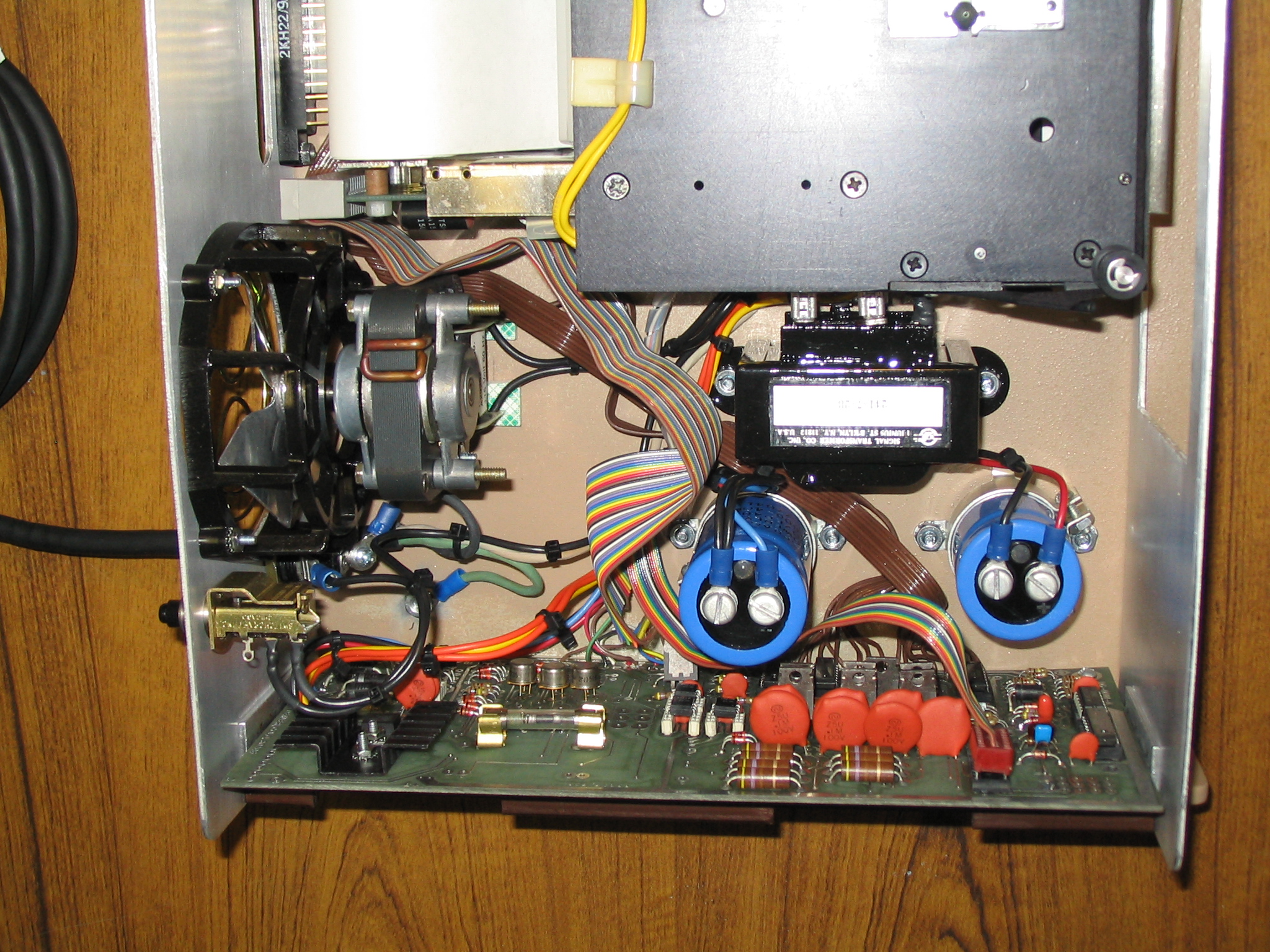
The fan seen in the photo's was destroyed. The housing had shattered,
and the blades were bent terribly. I used JB Weld to cast the missing
bits, and to repair the frame, with small brad nails strategically embedded in the mix
for more strength. I have found this to be a great technique, and this
time was no exception.
After connecting to my system, the completed printer took me forever to
tune and adjust. The platen setting vs. the software settings were a pain.
I must have done something a little off kilter in my restoration, since
the printer will not work with the default software settings. The impact
time had to be increased nearly to maximum, but with the altered software
settings, the printer works great!
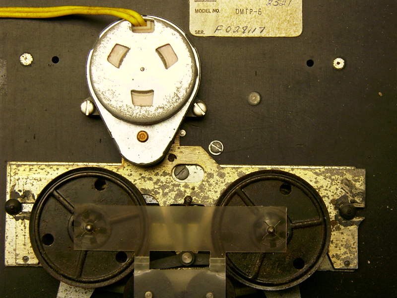
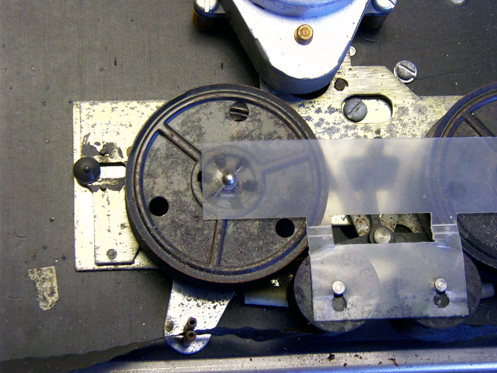
|
|
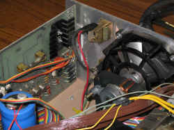
Weight of the fan has broken the housing
|
|

No lugs used on the caps--bad!
|
|

Rust, dust, and spider webs
|
|
| They say a picture is worth a thousand
words--here's fifty thousand words. :) Starting with...
The Before Photos
|
|

The printer, sans case
|
|
|
Rust view
|
|
|
|
|
|
Pressure rollers are destroyed
|
|
|

The hand print is rusted in place
|
|
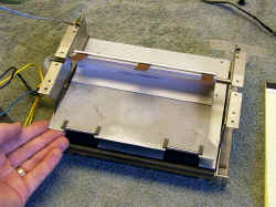
Paper guide, that's not dirt, it's rust
|
|
|
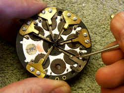
Print hammers were frozen in place
|
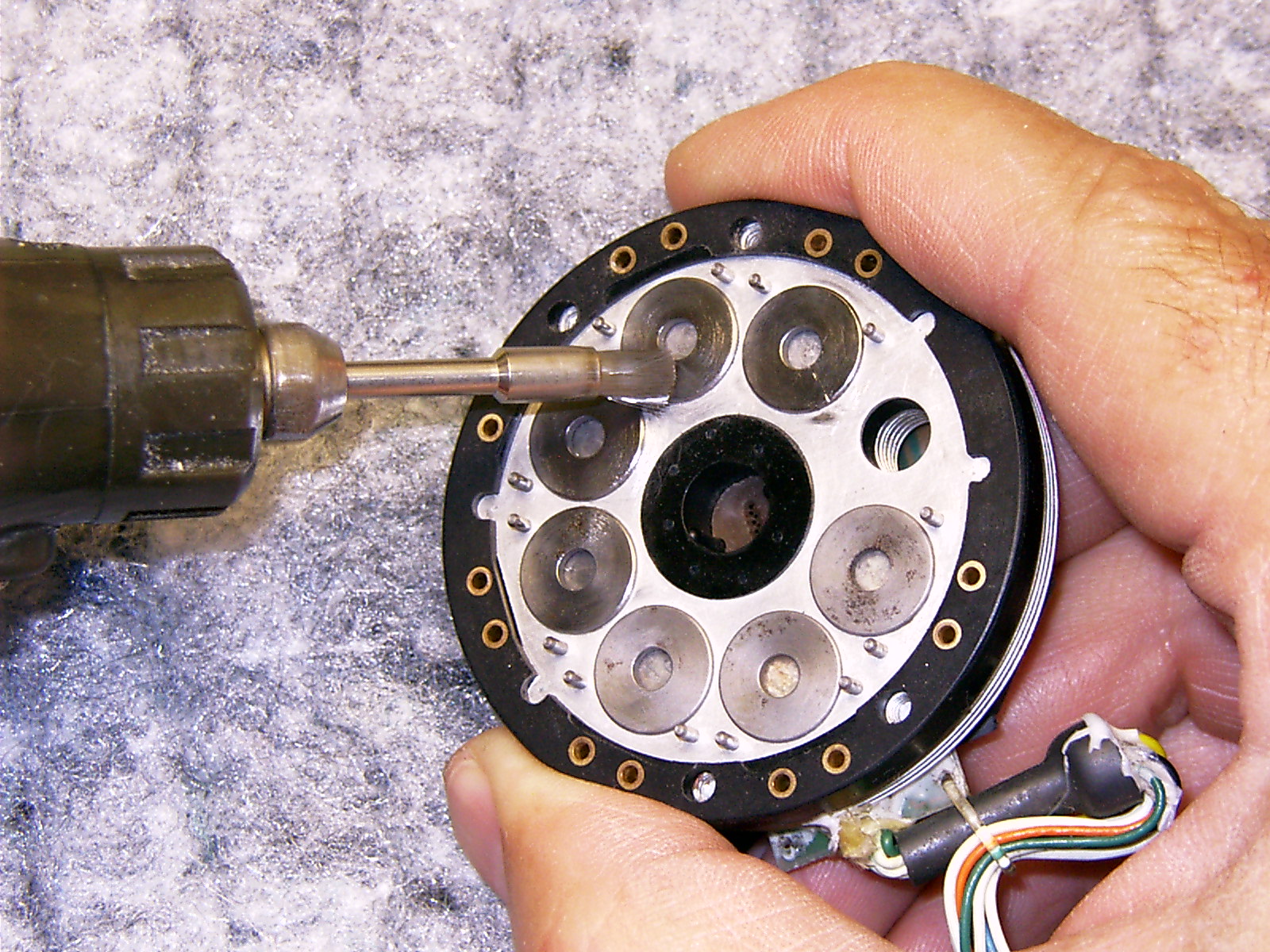
|
|
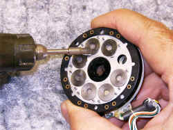
Rust removal with trusty Dremel
|
|

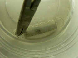
Reassembly--one hammer pin is broken
|
|

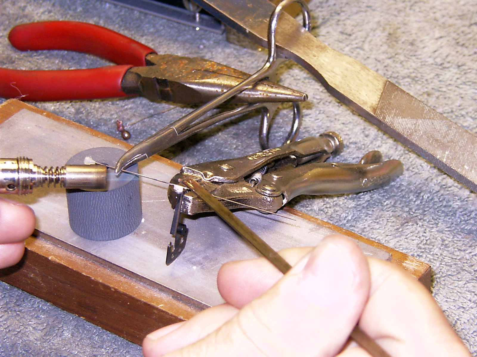
Welding a new pin in place
|
|
Sanding to remove that handprint
|
|
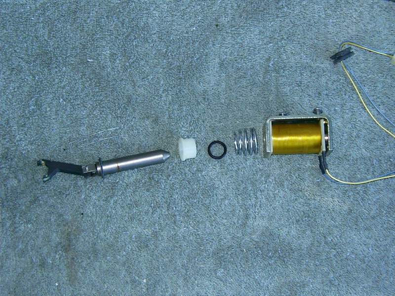
|
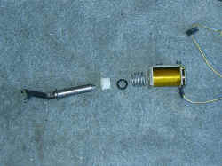
Cleaning the paper advance solenoid
|
|
|
Pretty rough
|
|
|
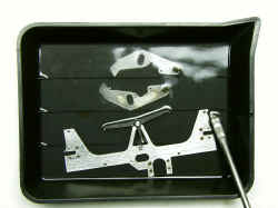
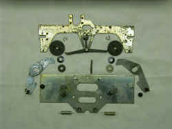
Sulfuric acid bath removes rust
|
|
|
Saving the springs
|
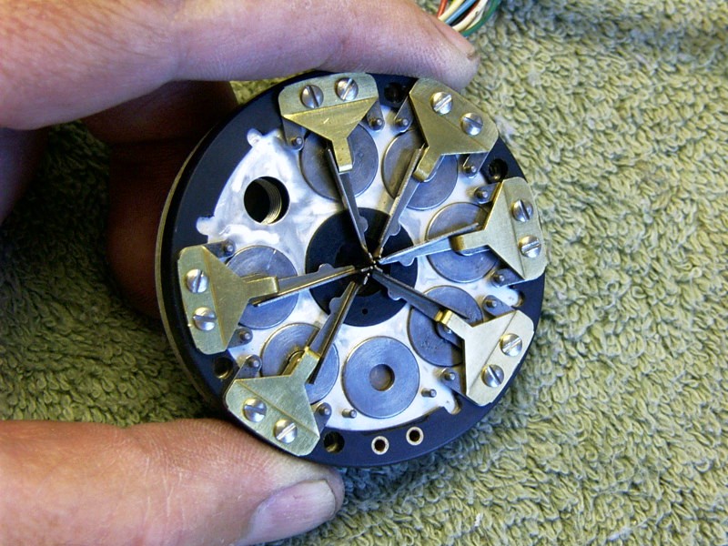
|
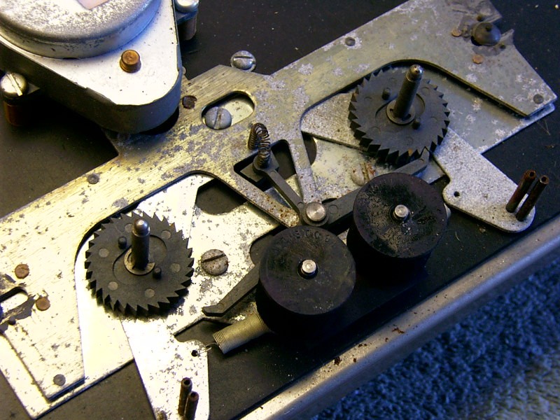
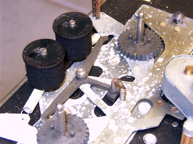
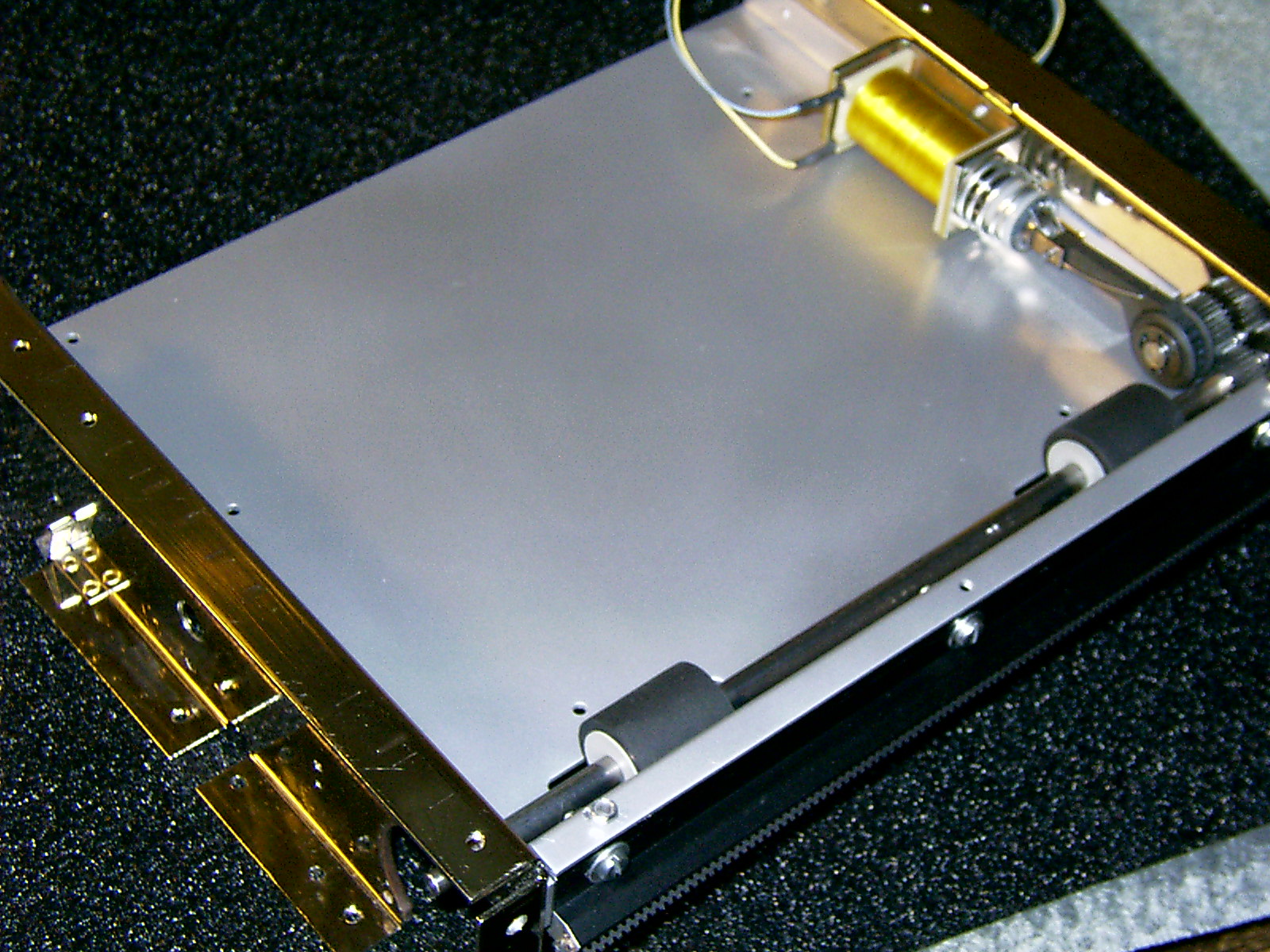
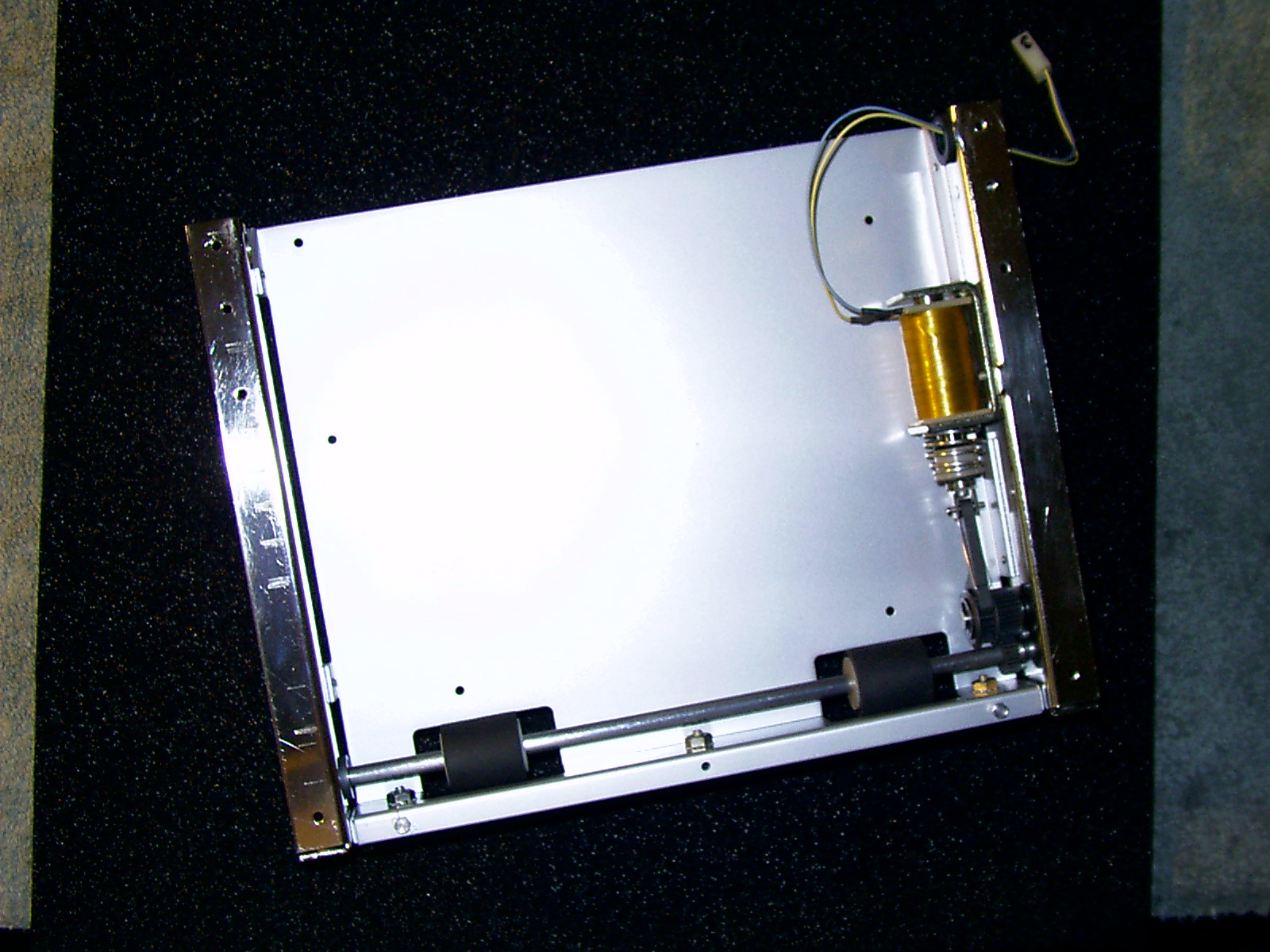
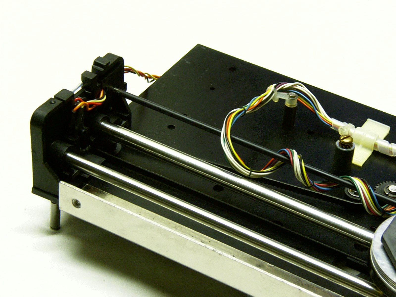
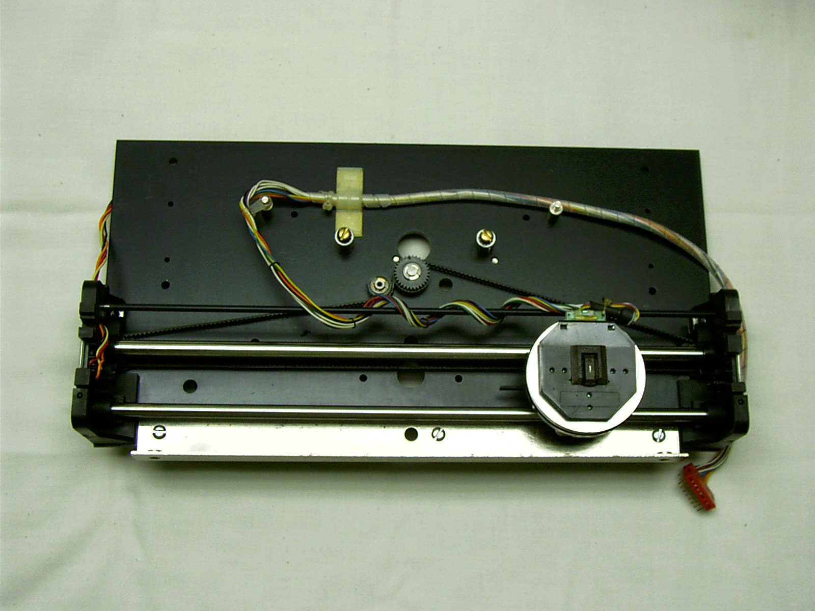
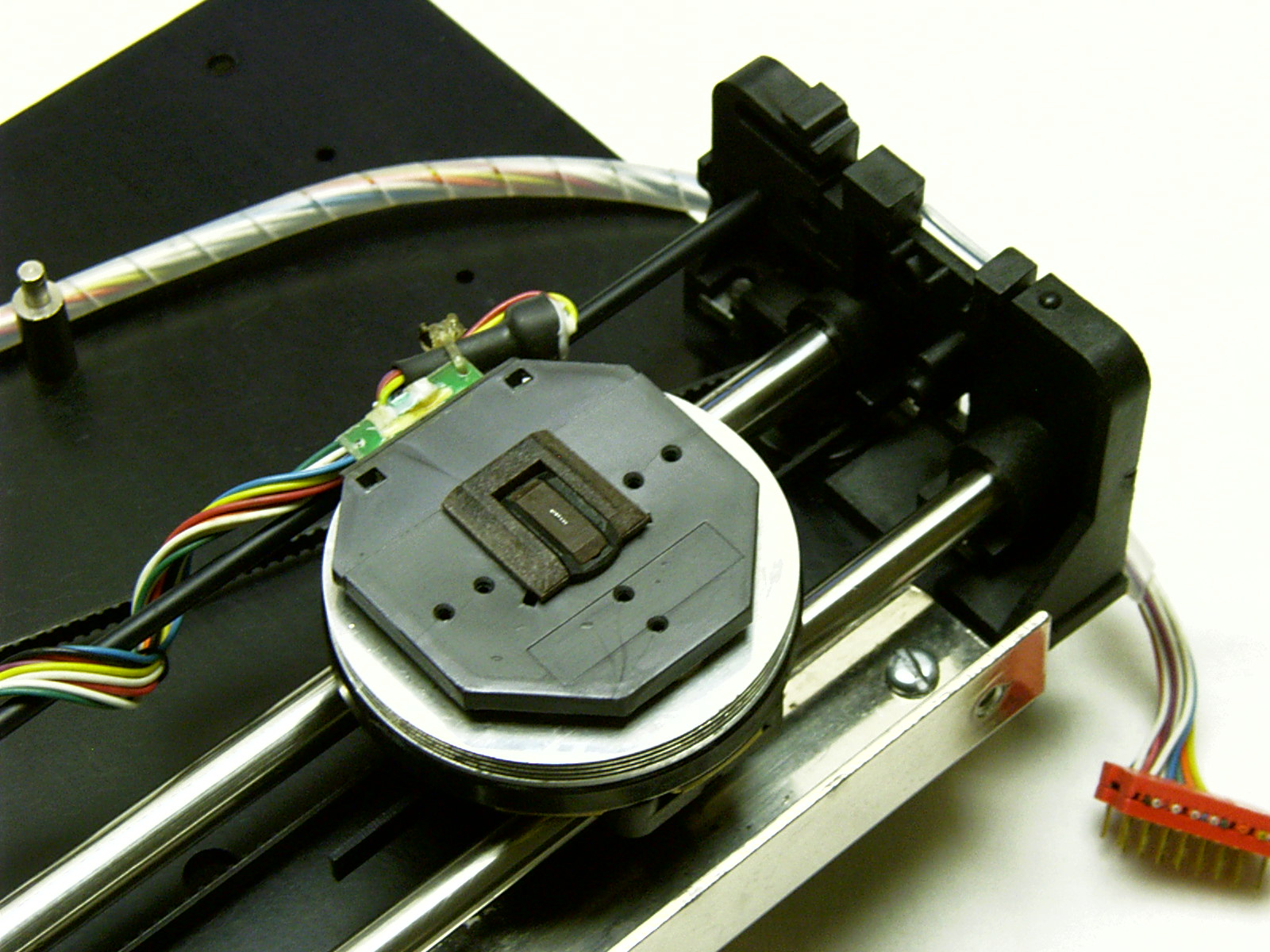
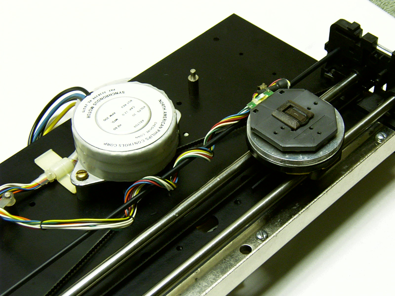
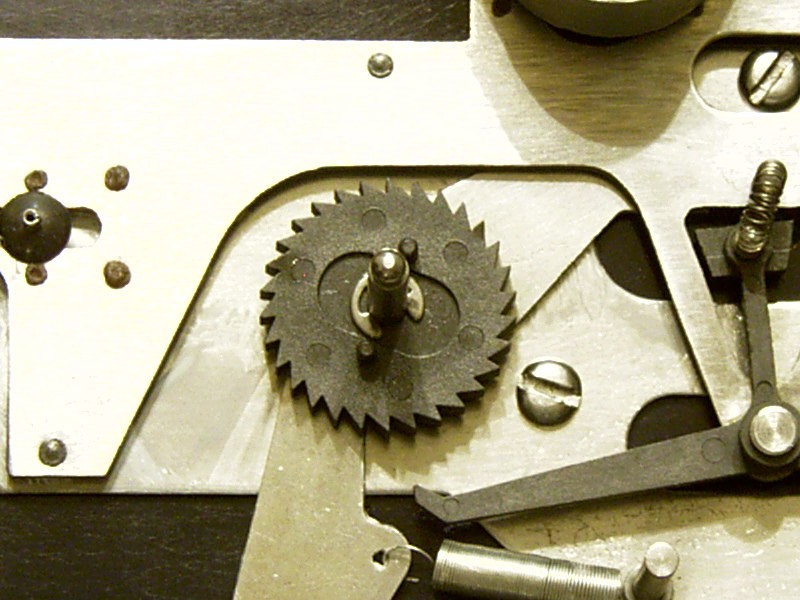
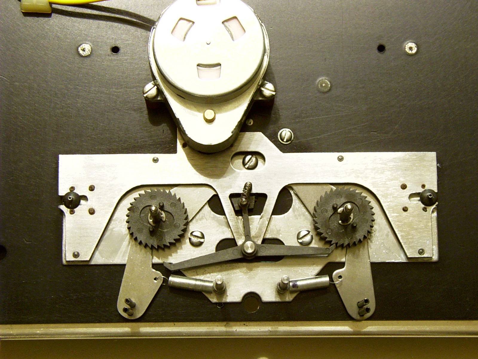
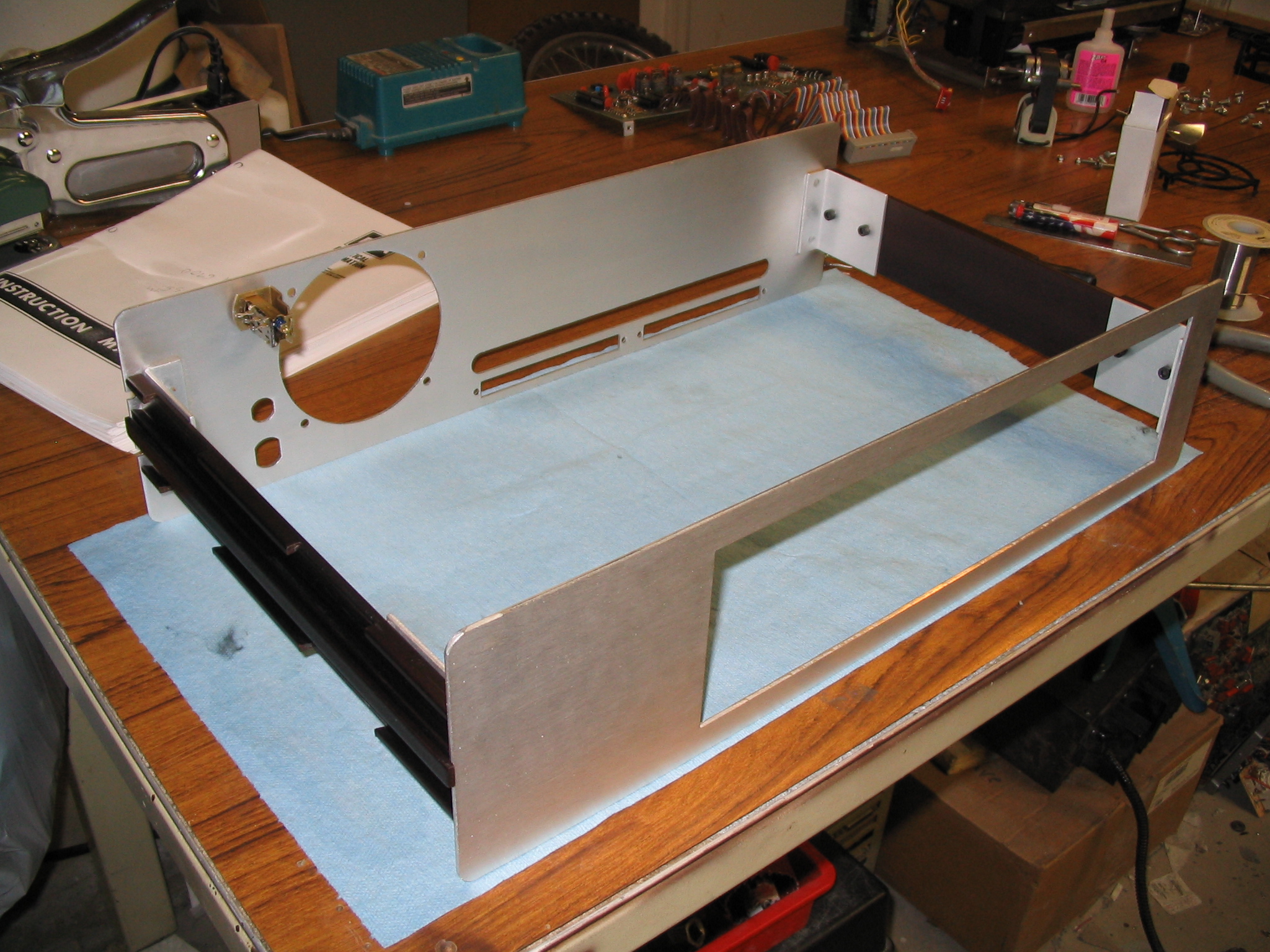
| Reassembly
|
|
|
|
|
|
|
|
|
|
|
|
|
|
|
|
|
|
|
|
|
|
|
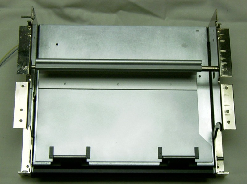
|
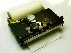
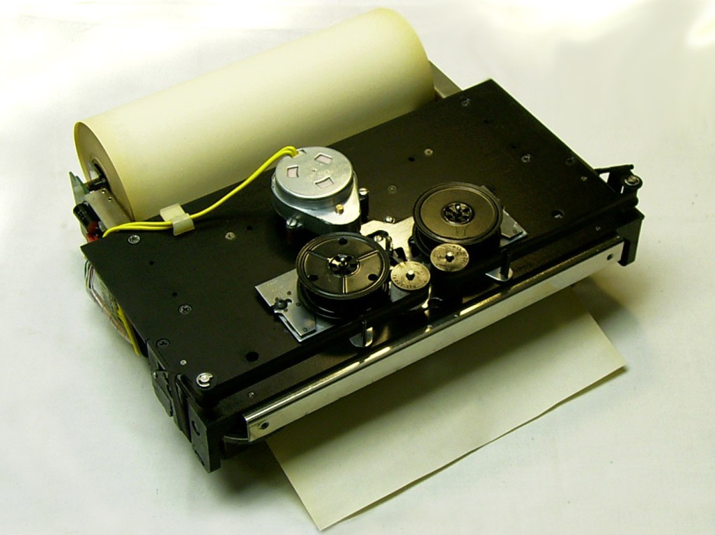
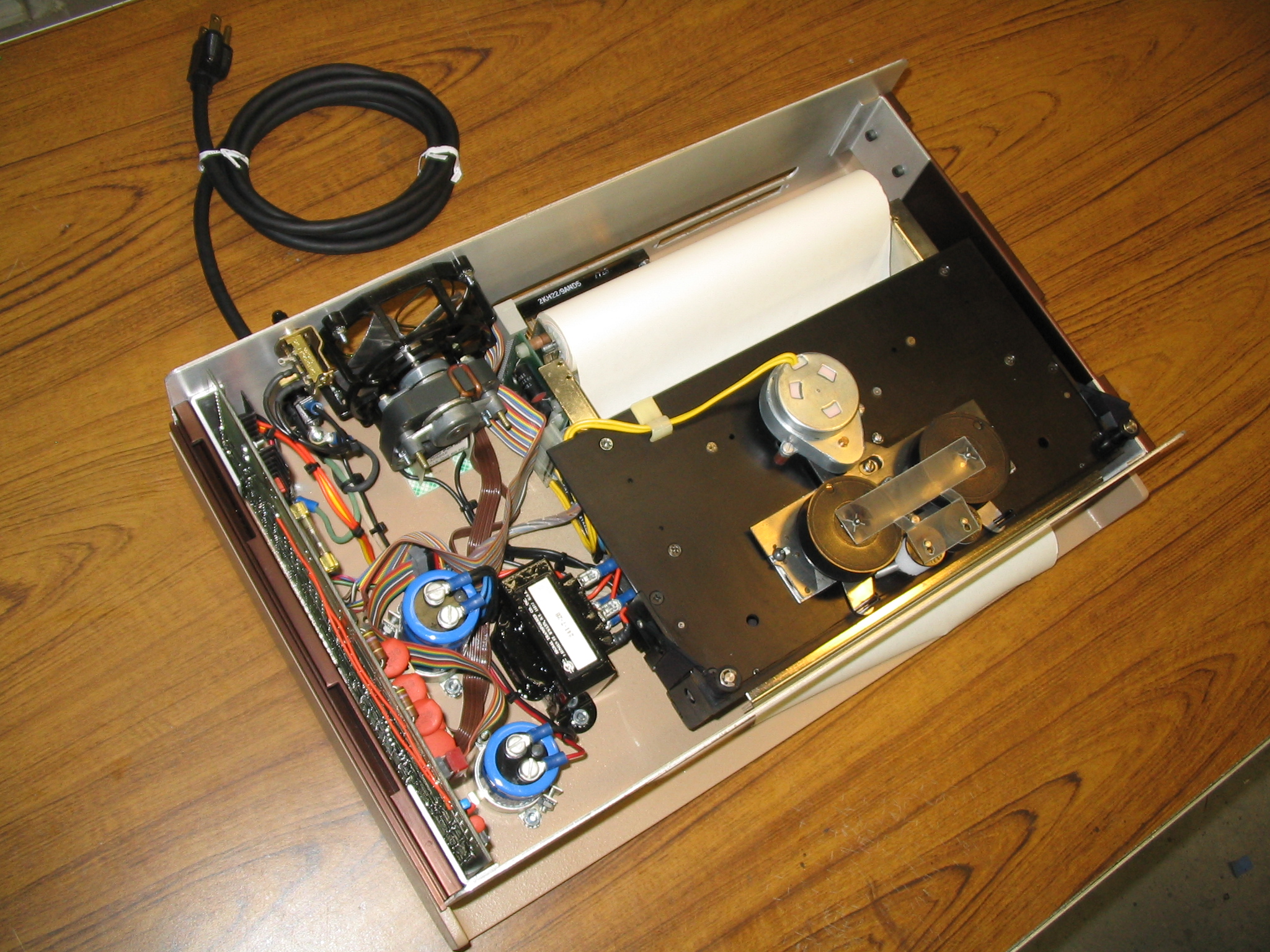
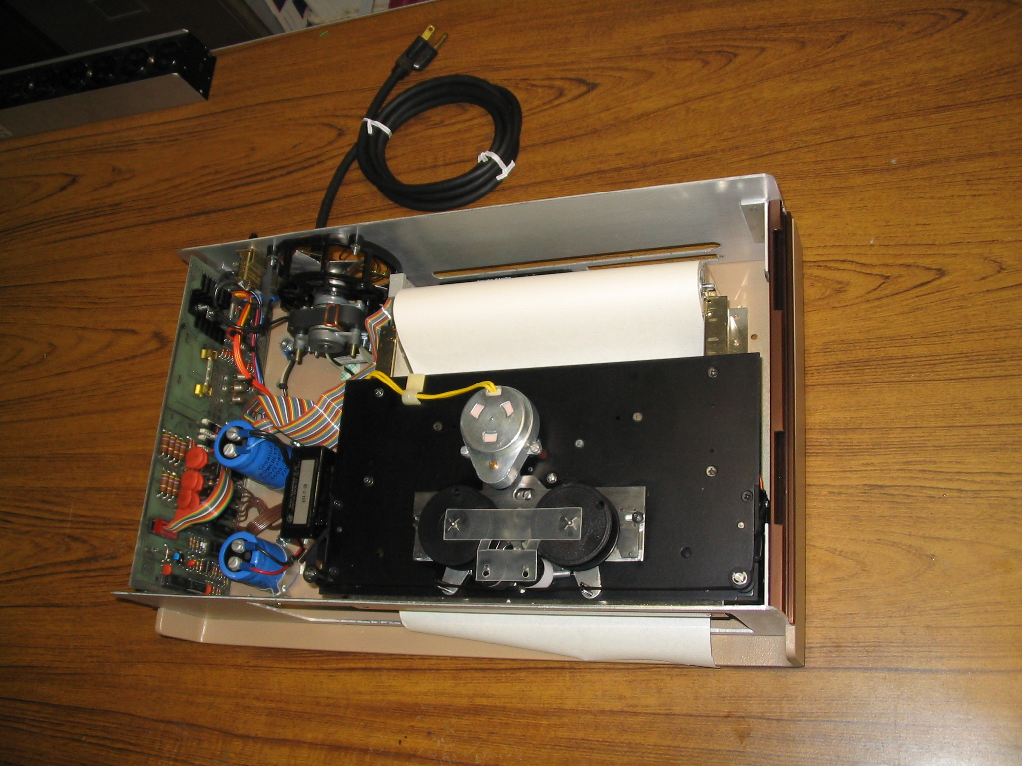
The printer, After
|
|
|
Final Assembly
|
|
|
|
|
|
|
|
|
|
|
|
|
|
|
|
|
|
|
|
|
|
|
|
|
|
|
|
|
|
|
|
|
|
|
|
|
|
|
|