|
IFR 1200 SS
Cushman CE-5
Airwave Inc.
My Collection
HP-01
Test Equipment
Model Rocketry
| |
|
|
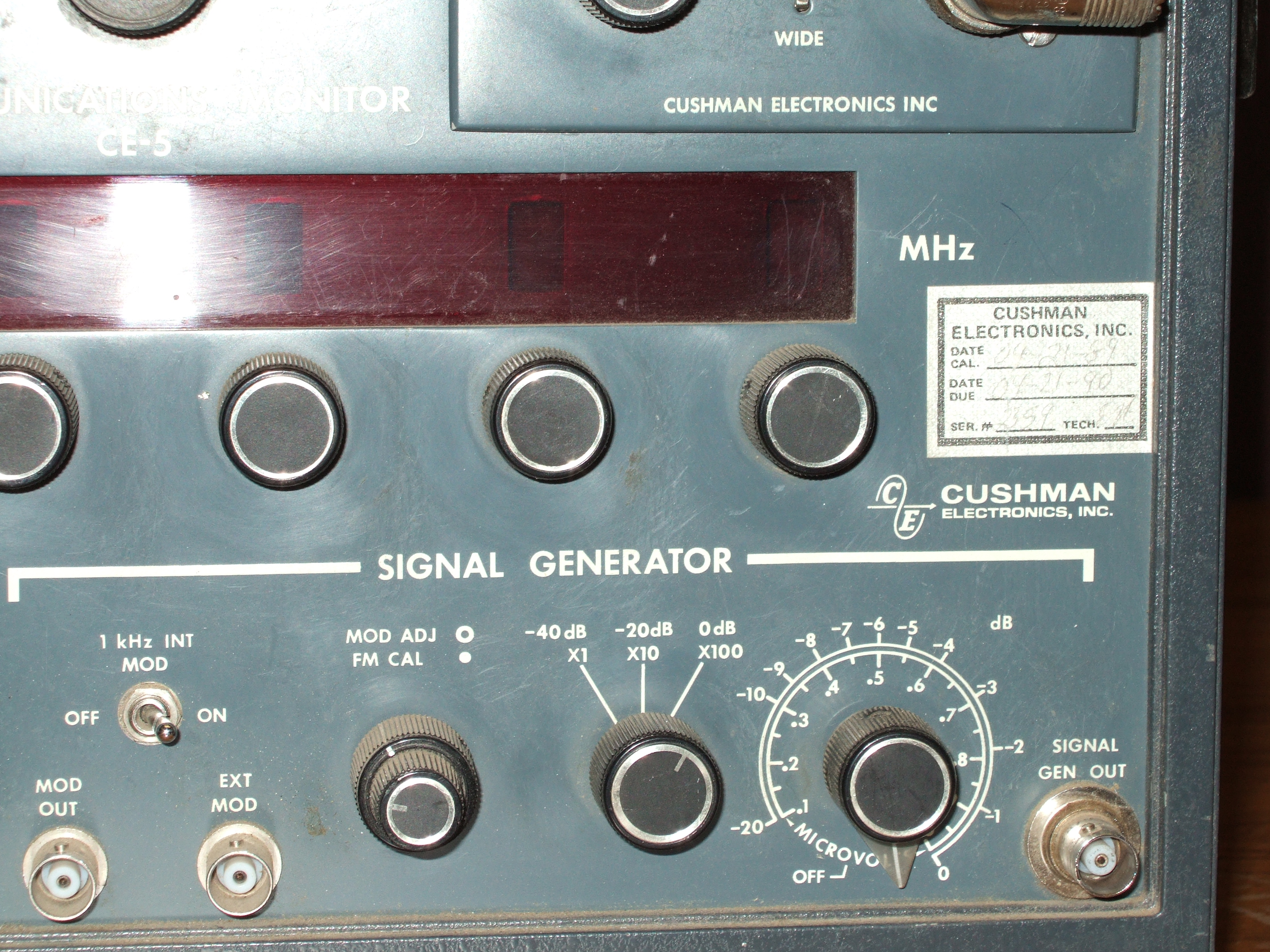
| Cushman CE-5
Cushman was a popular test equipment manufacturer based, I believe in
San Jose, California. They made all manner of RF test equipment from
service monitors and, spectrum analyzers to microwave test equipment like
selective level meters and signal generators. Nothing they made was
especially terrific in any way, but it was certainly usable by the target
customer base: the two-way radio industry. Their hey-day was in the late
seventies and early eighties, but technology moved faster than they could
adapt, and now they are history...
I have a half dozen Cushman monitors I picked up from salvage in rough
condition. They were used by a large company to service radios in the
field and at the bench, so they all show signs of travel. None of them
worked as delivered, but they all look serviceable. I chose to do the CE-5
first, because it appeared to require the least amount of effort to get
going -- I needed an easy success at the time!
My first Cushman was a CE-6, way back in early the eighties, very
similar to this one, but wider frequency range. This was another reason to
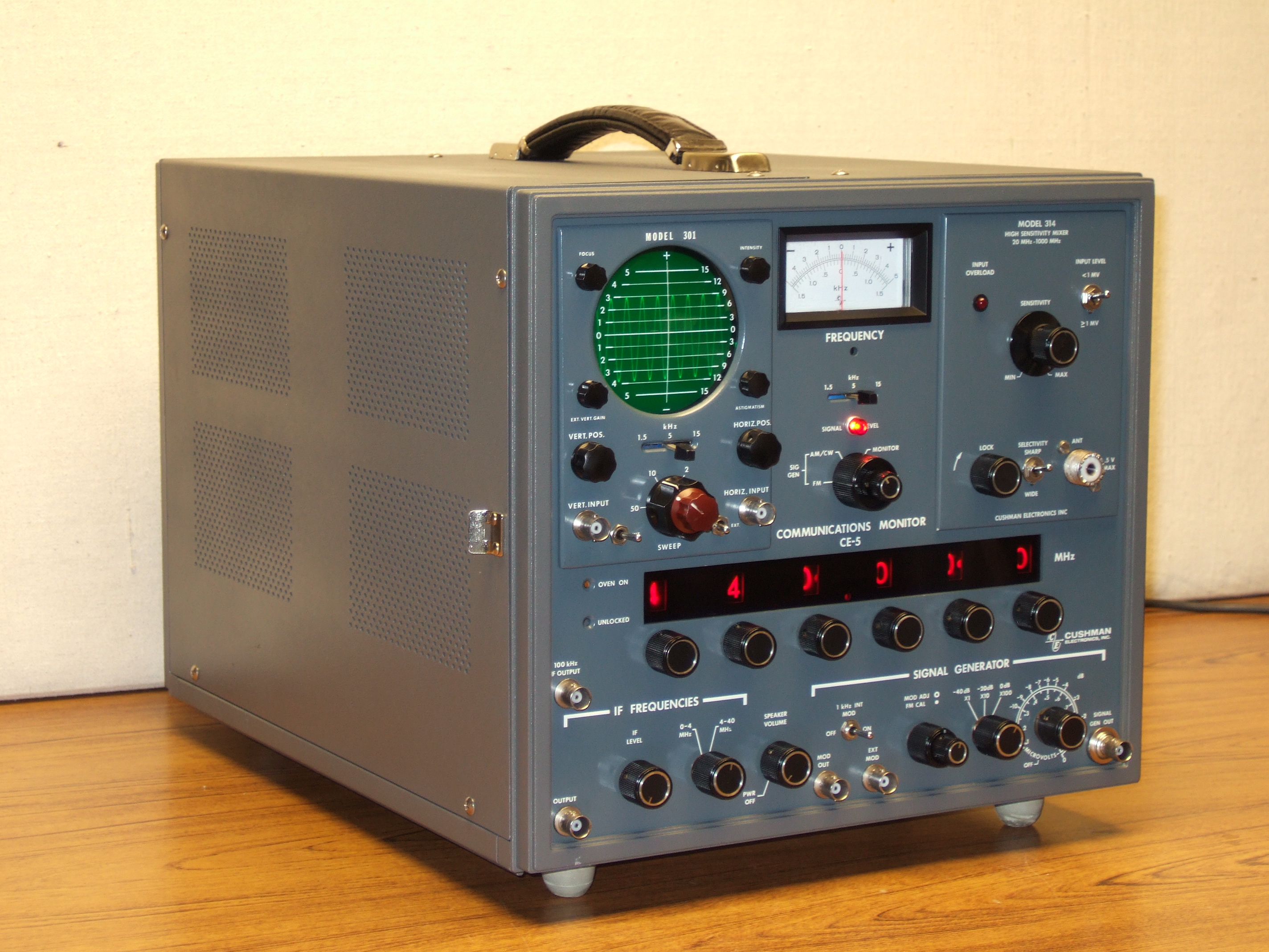
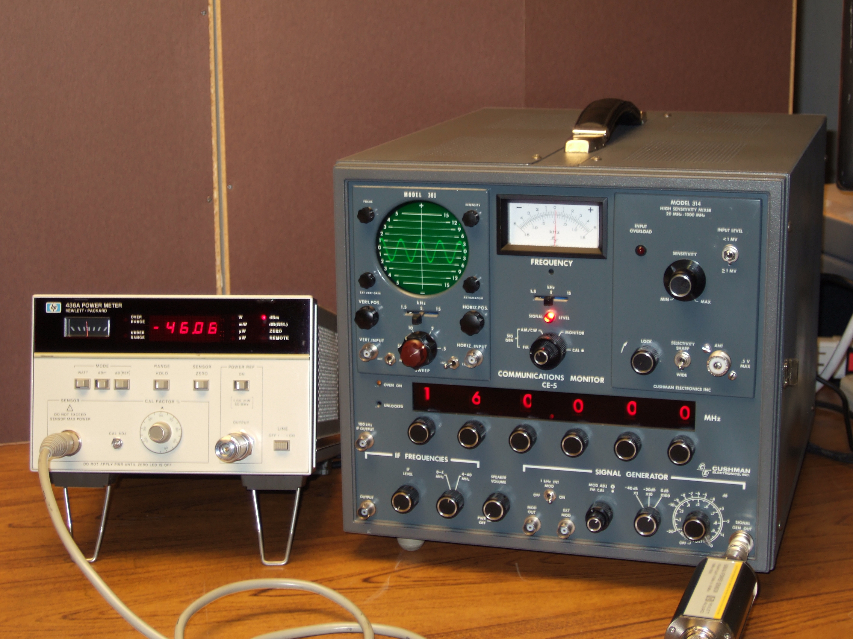
start with the CE-5: familiarity. The CE-5 has a directly tunable range of
20-519 MHz, and by using IF frequencies and harmonics, can be made to work
from 0-1000 MHz. It generates signals up to -47 dBm, with AM or FM
modulation, and demodulates FM with deviation measurement and frequency
error measurements. The time base in this thirty year old machine is
tremendously stable, exceeding my ability to (easily) characterize even
with my 1 PPB frequency standard. This will make a great HAM radio test
set!
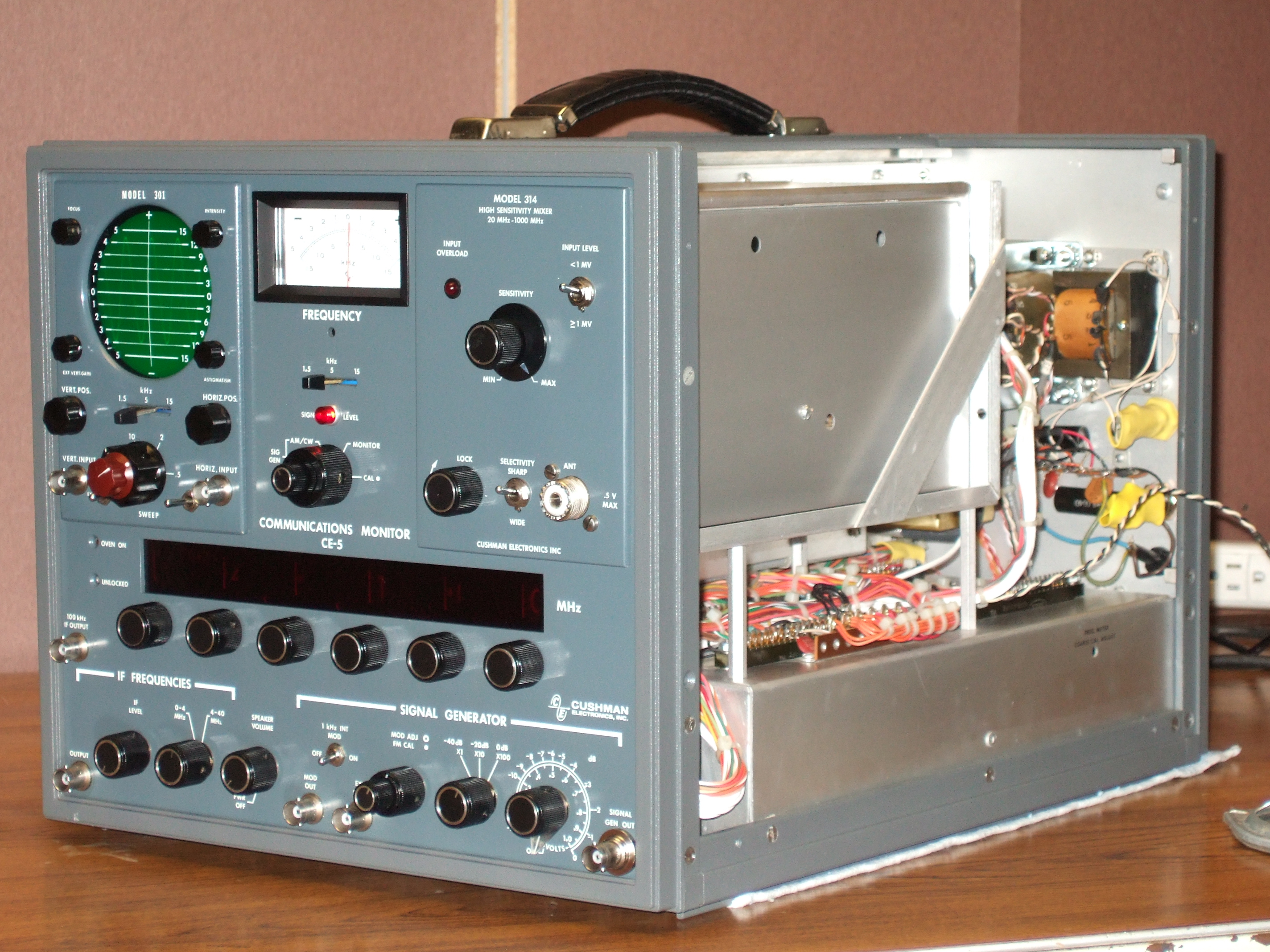
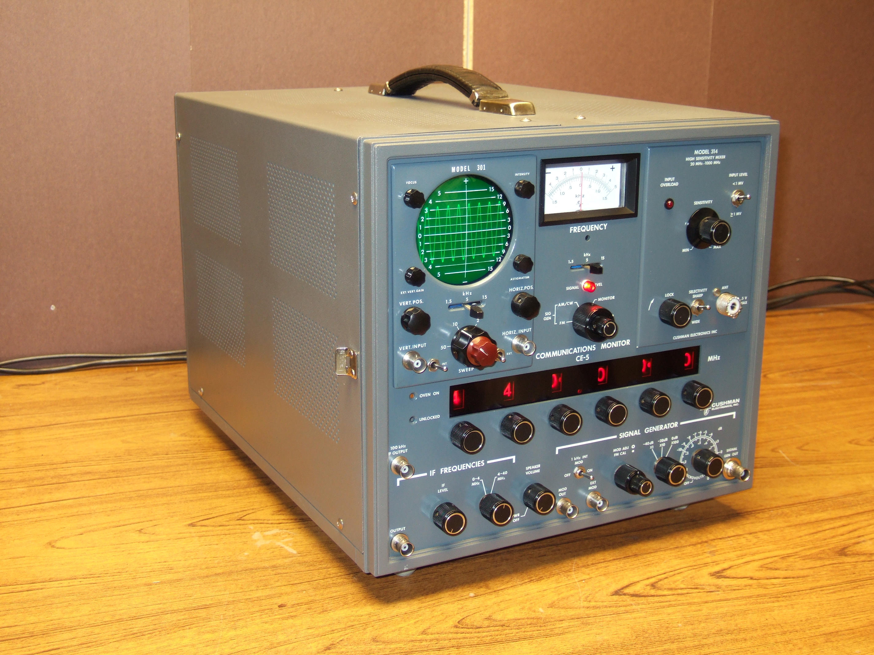
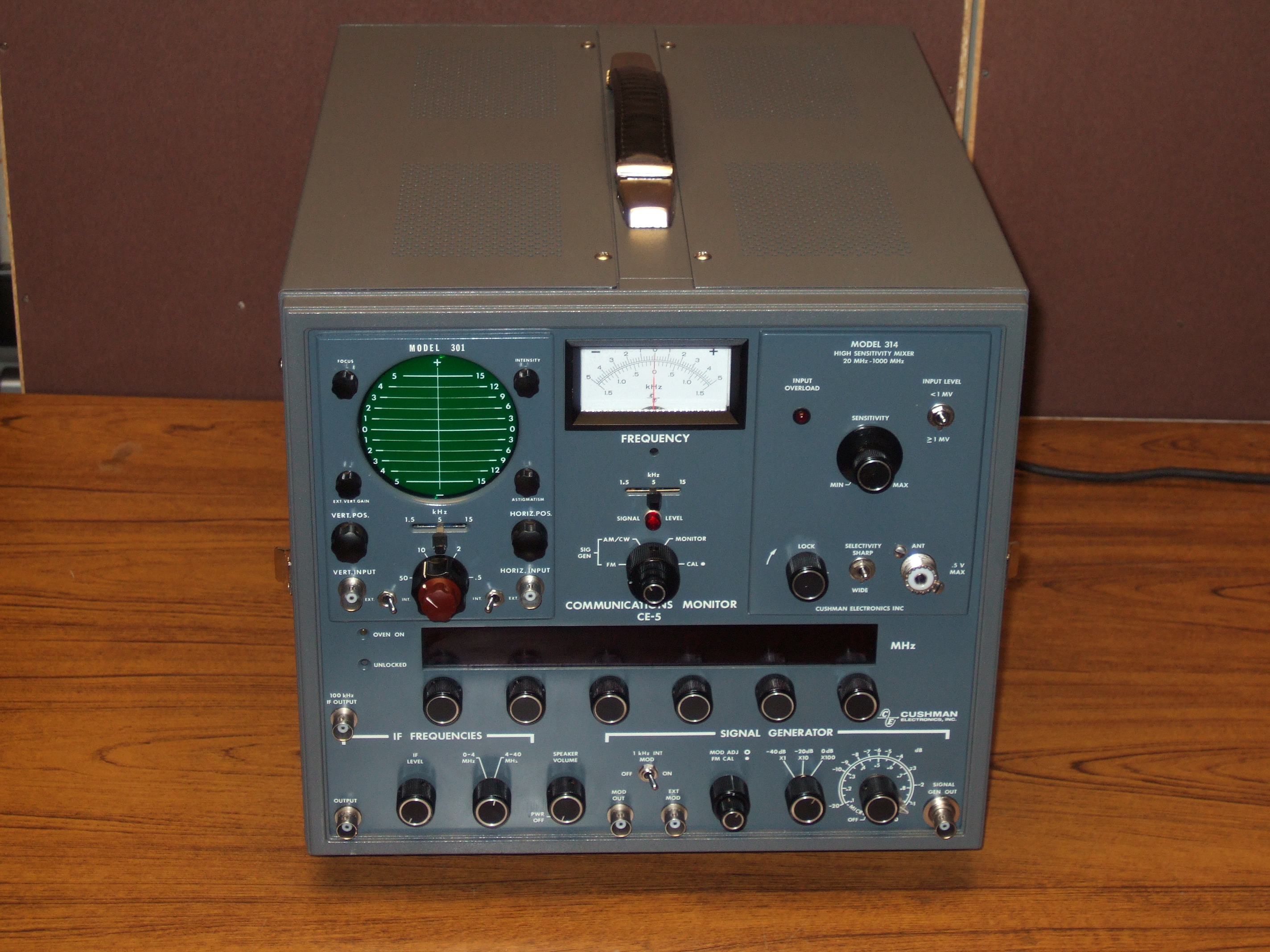
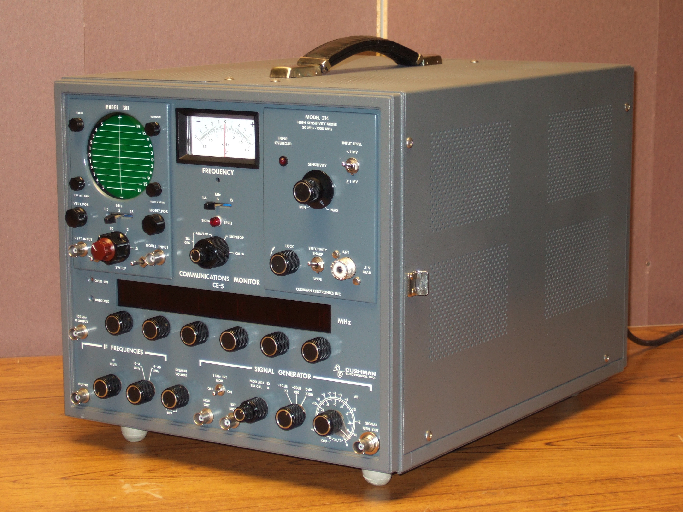
|
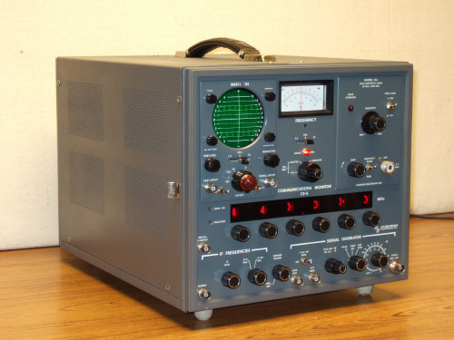
Restored and pretty Cushman CE-5
|
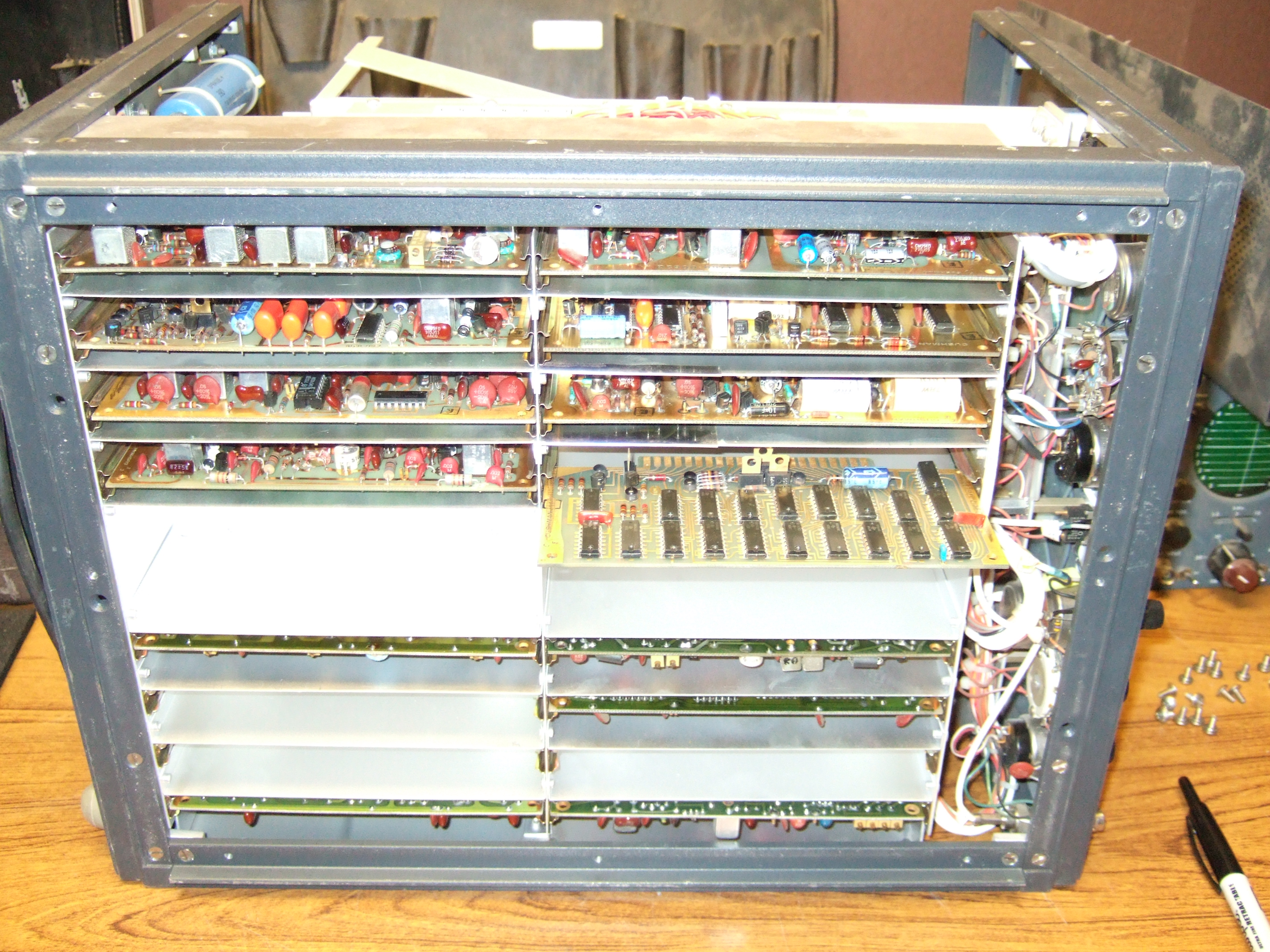
| Restoration
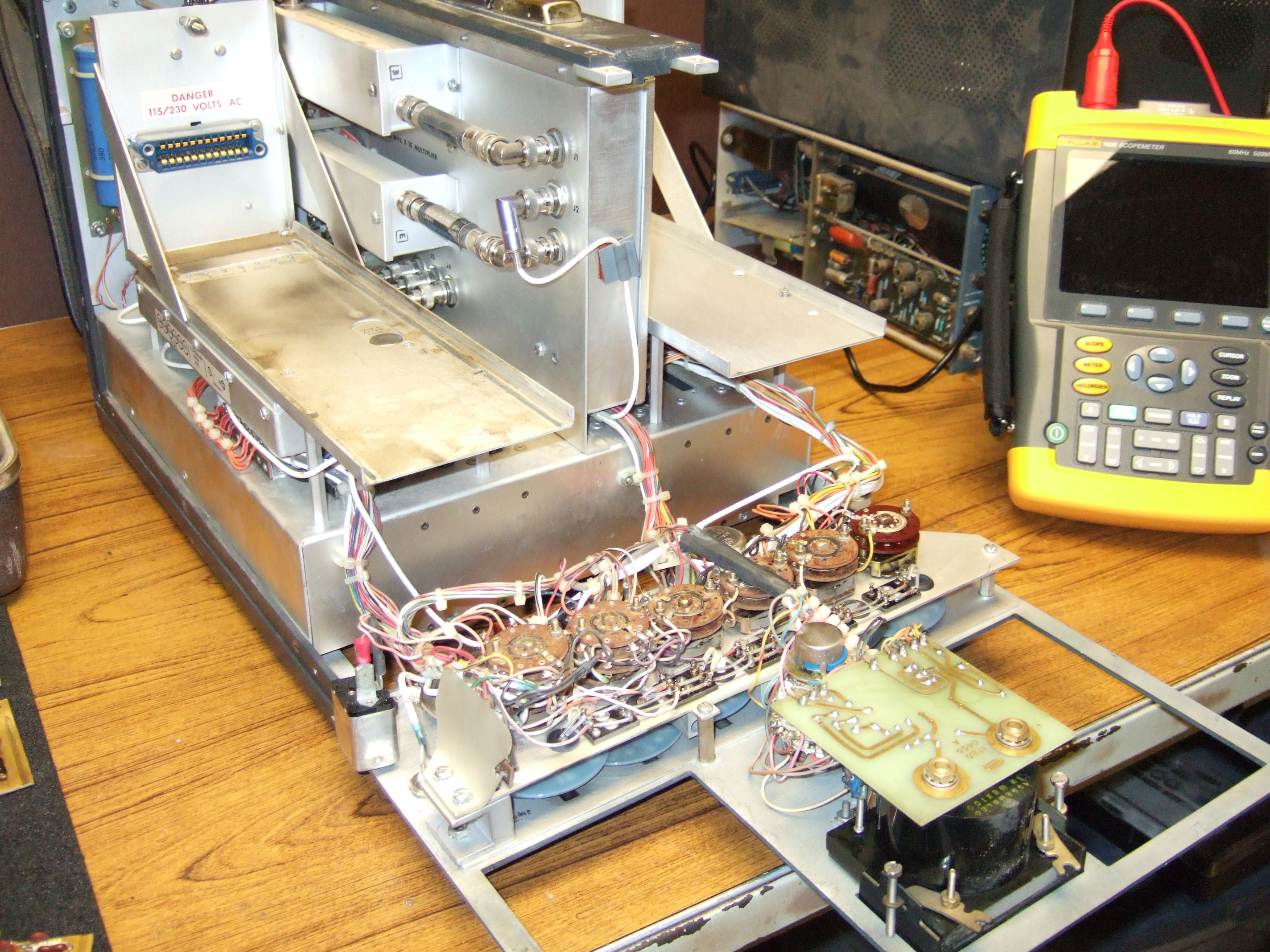
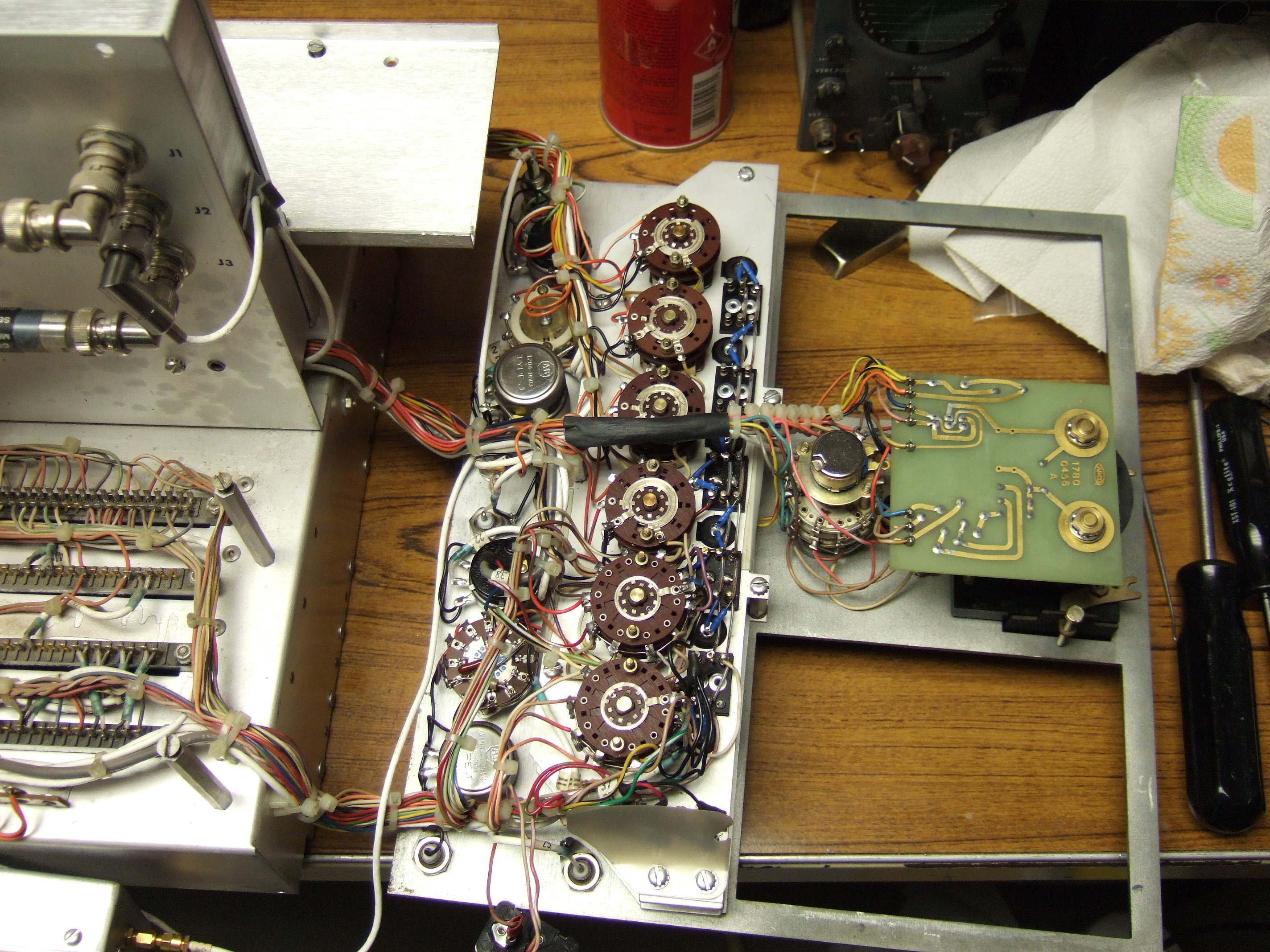
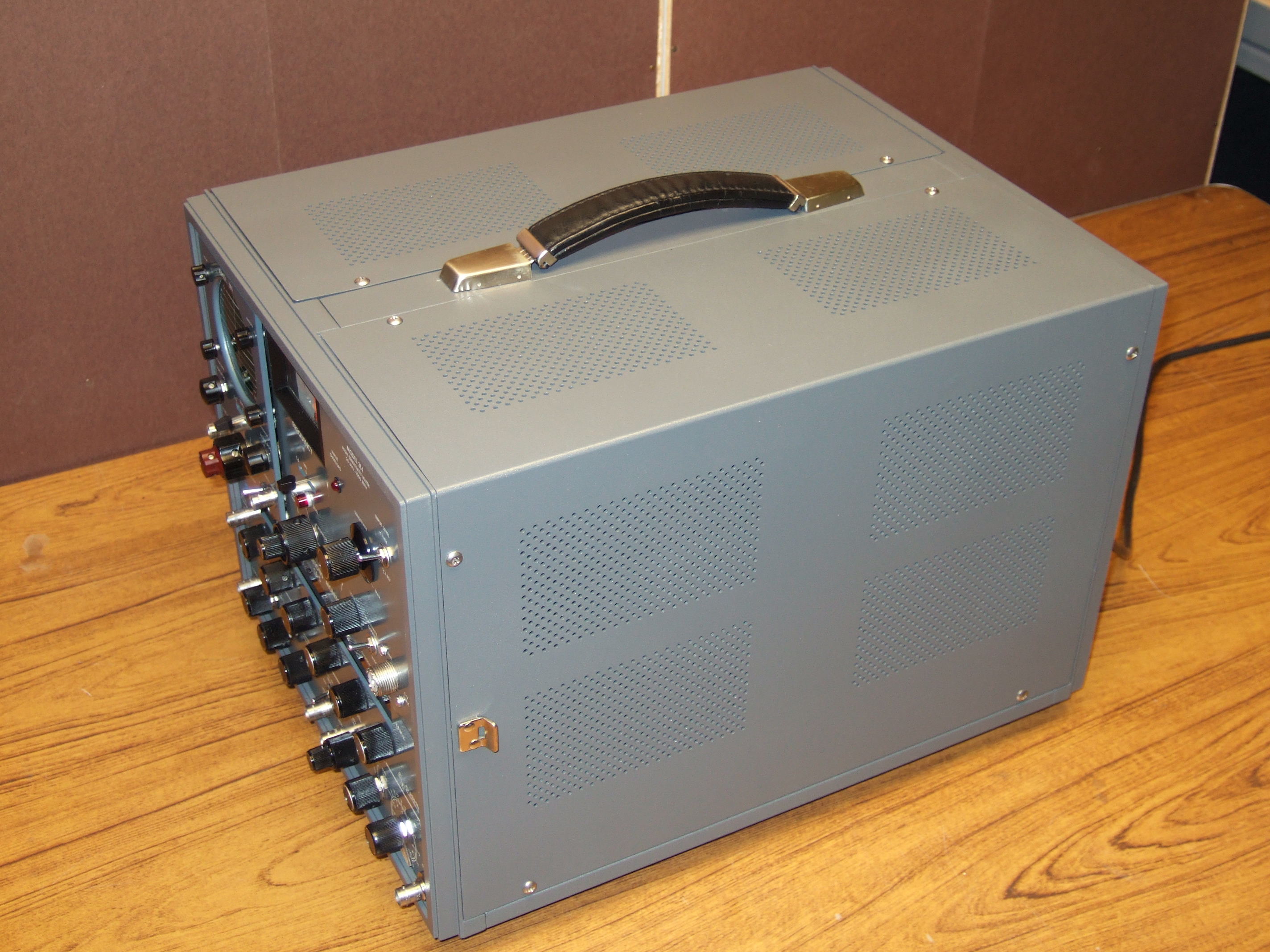
I started, as I usually do, by tearing the machine down and cleaning
everything. Each of the dozen plus modules were removed, cleaned, and
repaired as needed. Next, the chassis was scrubbed clean along with all
the switches and pots. This was done in steps: I actually used Windex and
a toothbrush to clean most everything, followed by rinsing with clean
Windex, and then blowing all the moisture away with compressed air. The
Windex was an experiment chosen because of its fair cleaning power and low
residue, it worked fairly well too. Next, I used a plastics-safe (Tested!)
contact cleaner to remove any Windex residue. The type I used was highly flammable,
so precautions were observed. The excess contact cleaner was blown away
with compressed air. Finally, contact restorer was used on all contacts,
pots, and switches. Some of the boards had thirty-year old solder flux on
them, this was removed with flux remover before the cleaning. Surprisingly,
I found no loose screws, anywhere! What I did find was that Lock-Tight or
something similar, had been used throughout -- Go Cushman!
Once all this was completed, I pulled all the incandescent bulbs out
and tossed them. They were all replaced by 7000mcd LED's. These were wired
in with a rectifier diode and a current limiting resistor. The rectifier
was needed due to the fact that the bulbs had been fed with AC. This
worked great! No more bulbs to replace, ever again.
The housing and trim was primed and repainted with a nice "Dark
Pewter" paint closely matching the original in color and texture.
self etching primer was used because the metal is aluminum, and paint will
not adhere to aluminum unless is is totally clean and free of oxidization.
The self etching primer assures that. The paint is baked on in my wife's
oven at a temperature of 175º for about six hours. (My wife hates the smell! I
have to wait until she is out of town to do this! :) The control surfaces
were cleaned and restored with WD-40 -- Yes, I know. Everyone hates WD-40.
Hear me out: WD-40 is an excellent cleaner for grease and dirt, and when
wiped dry, leaves a finish that will dry hard--varnish, that protects the
old paint somewhat. May not be the best, but it works quite well.
|
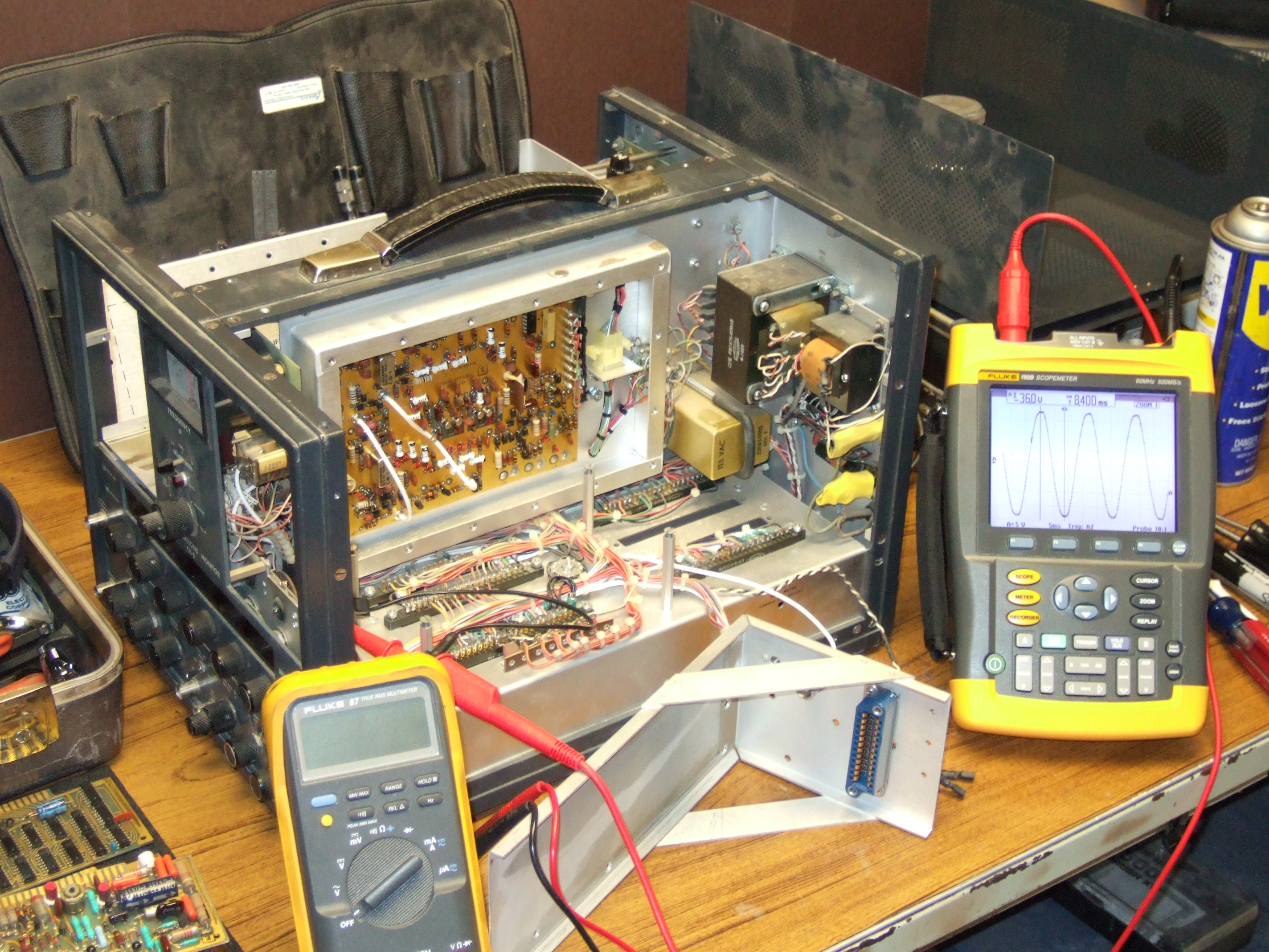
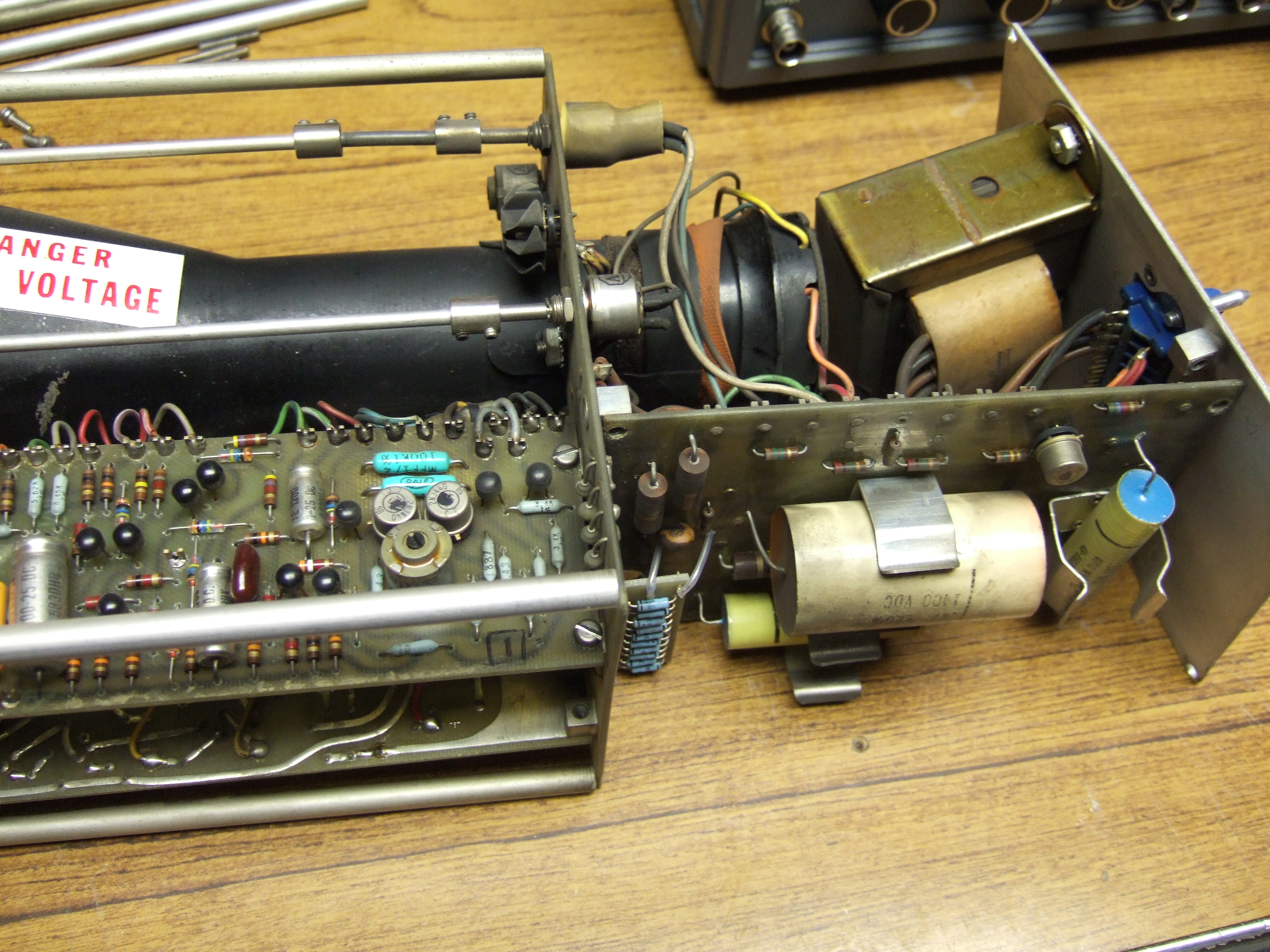
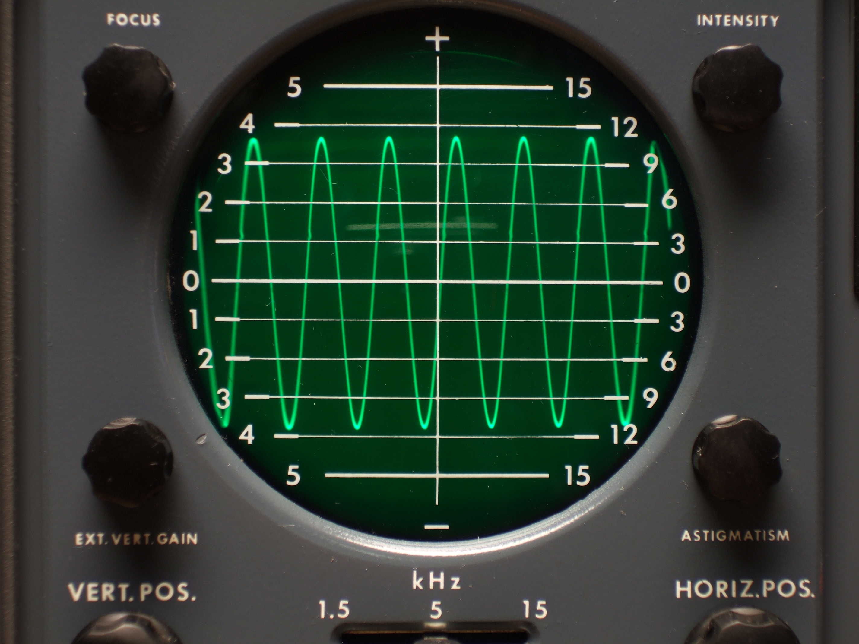
| Scope Tube
The scope tube was on the dim side, usable but noticeably stricken with
cathode poisoning. I ran it through a twenty-one hour rejuvenation process
I found in a Hewlett-Packard memo. This was the first time I had ever
tried it, and it made a big difference. Most notably, the brightness
control acted linear again! Before, it was dark until almost at full
brightness, and would then brighten up all at once. Now it brightens up
gradually. It is no brighter than it was before, but now it works like it
should. HP recommended that the rejuve be done twice, but I stopped
while I was ahead -- just once.
In a nutshell, here is the process:
Isolate the filament from the original power supply and connect to an
AC transformer through a Variac. Then follow the Voltages and durations in
the chart. (I used a 12.6 Volt transformer through my Variac -- This
allows a variable output of 0-12.6 Volts AC. Some people use DC for this
because it is easier to come by, but filaments were designed to operate
from AC, not DC, and many experts suggest that DC will be less effective
at best, and damaging at worst.) Note that the last five steps are
performed with the anode and cathode at operating voltages. Be sure to
check the maximum potential difference allowed between the cathode and the
filament!! You may need to have a resistor in place to raise the potential
at the filament, which will be dangerous! Use brains and caution! Be aware
that your isolation transformer must be able to withstand the isolation
Voltage as well!
If you plan to try this, read this stuff first: CRT
Restoration for the (Brave) Experimenter and my HP
memo
|
| Filament
Voltage as a % of rated |
| Step |
Duration (Minutes) |
% of Rated Voltage |
| 1 |
5 |
34% |
| 2 |
2 |
44% |
| 3 |
2 |
65% |
| 4 |
2 |
102% |
| 5 |
2 |
124% |
| 6 |
2 |
161% |
| 7 |
90* |
124% |
| 8 |
390* |
117% |
| 9 |
295* |
110% |
| 10 |
200* |
107% |
| 11 |
270* |
102% |
| * Cathode
& Anode At Operating Voltages |
Tube Rejuvenation Process
|
|
| Calibration and Disposition
Calibration information on the CE-5 is unavailable. I did find a copy
of the manual online, a terrible copy with limited service information.
The calibration in the manual was limited to trimming, rather than full,
detailed instructions. This was enough to get the monitor in usable
condition, but I am not willing to risk throwing it out of working
condition to experiment on calibration. Monitor functions work well,
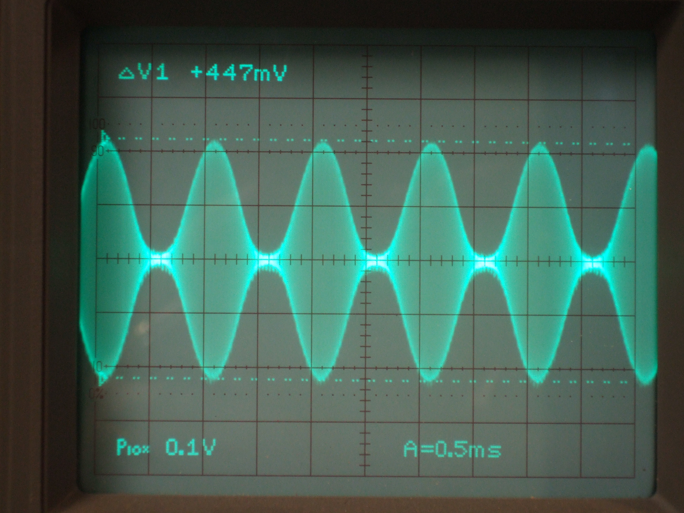
deviation measurements are reasonably close, and output levels are very
usable, though off by as much as +10 dBm. Deviation was checked using the Bessel
function -- a very simple and accurate method. The frequency accuracy is better
than 0.0036% and short term stability after warm up is better than I can measure --
Most excellent.
I am the process of trading this monitor for a SWTPC
6800 -- Yippie!
|
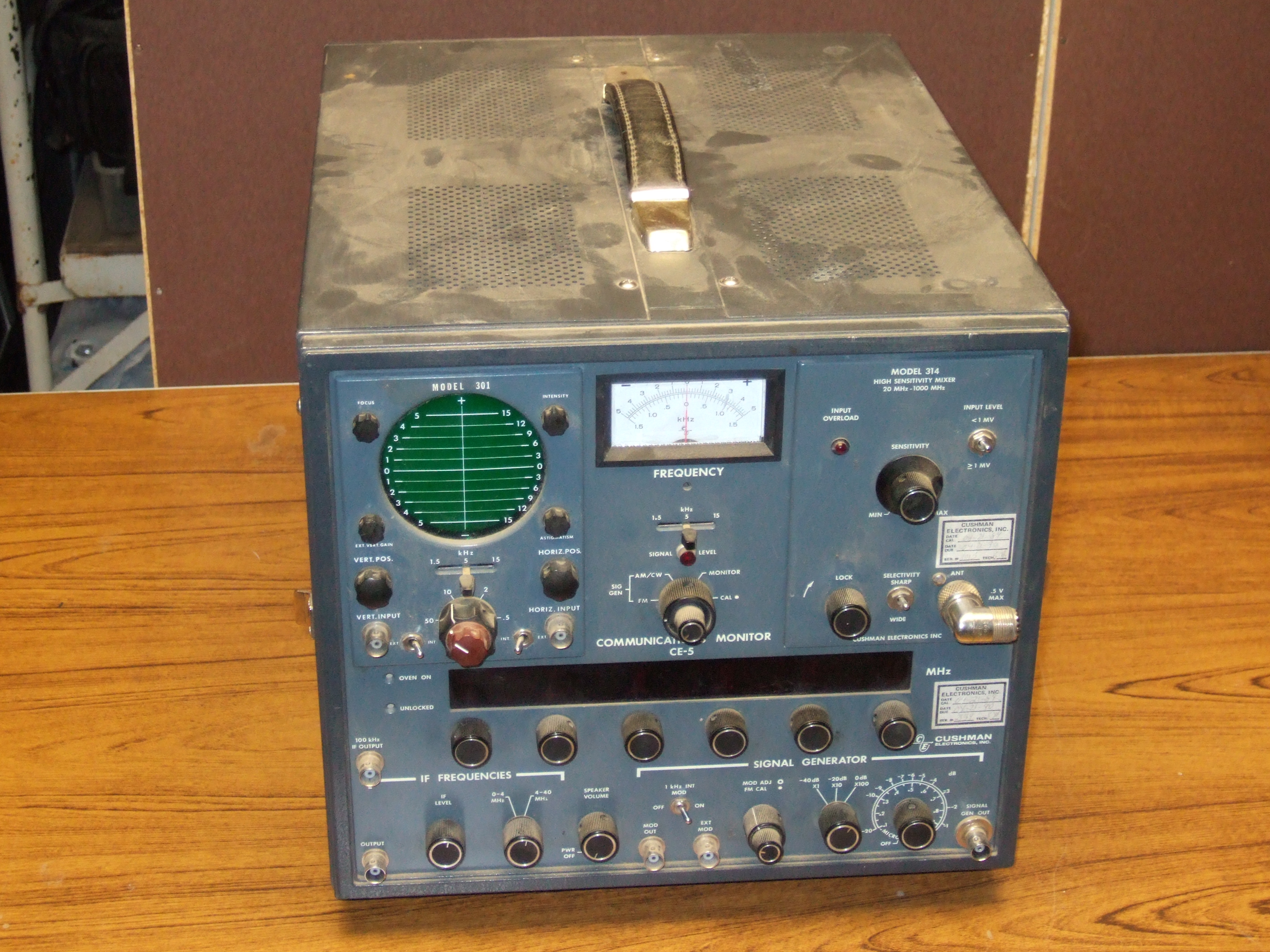
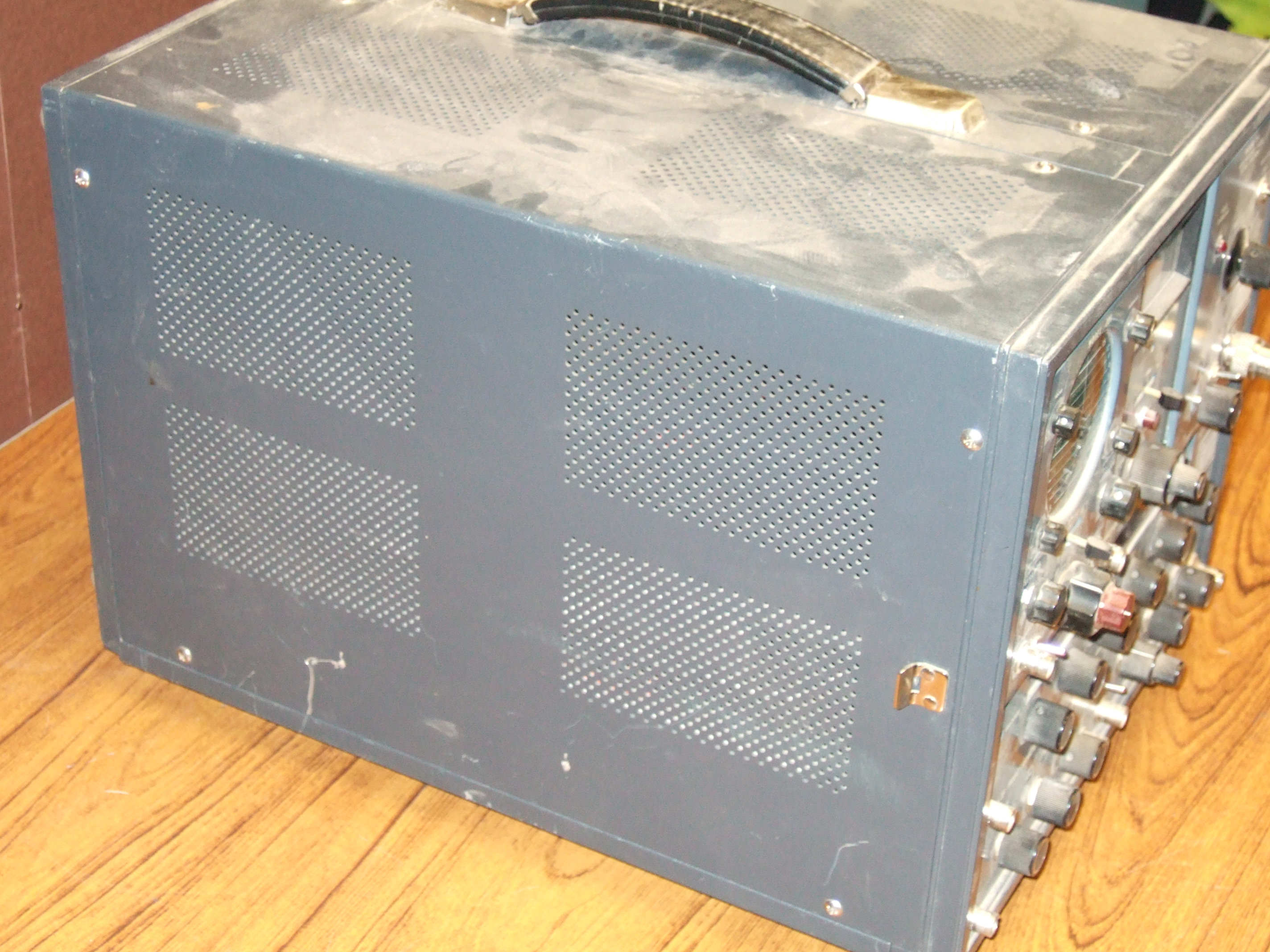
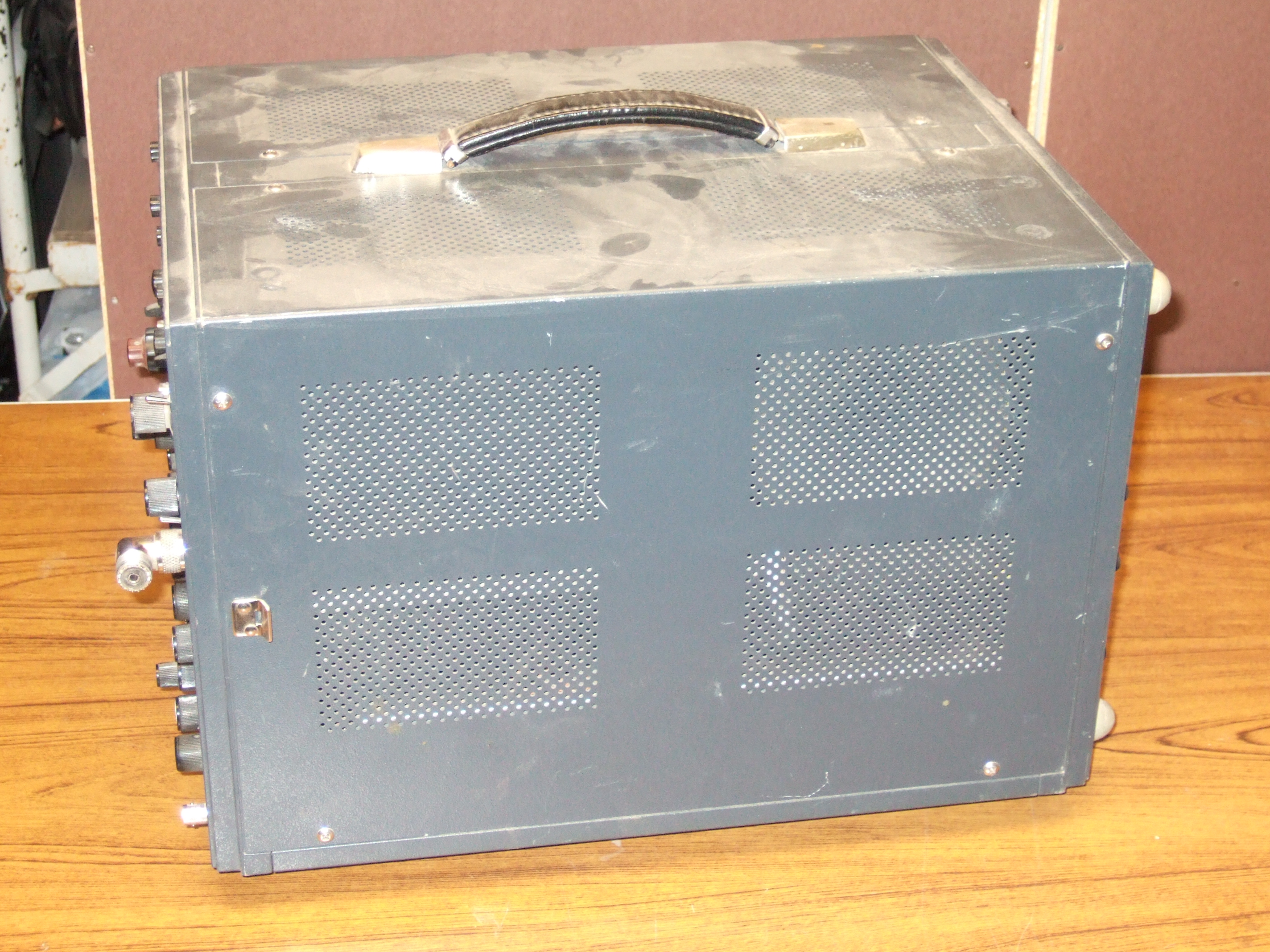
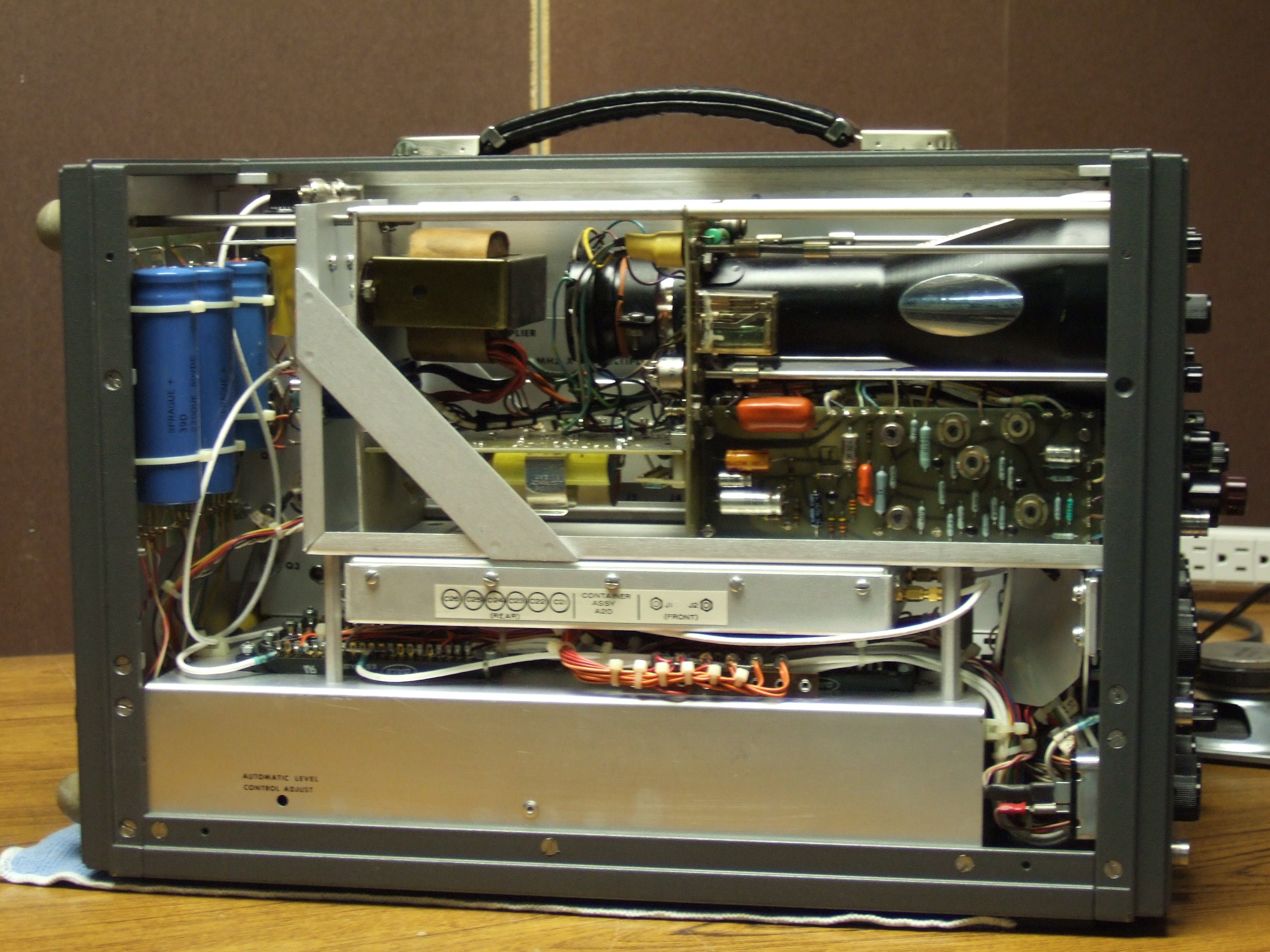
| And now, The Before And After Pics...
Before:
|
|
|